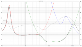
Yes, at the moment the best I can achieve in terms of impedance is just over 3 Ohms. That mid range is very misleading to be called a 8 Ohm driver. I even double checked my data to check I hadn't accidentally downloaded the wrong files. I might be able to improve it slightly but not by much. The only way I can raise it much higher is to reduce the sensitivity of the whole design and resistively pad the mid slightly.
If you need 8 ohms for your amp it might be better to look for a different mid.
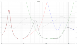
See attached impedance plot
If you need 8 ohms for your amp it might be better to look for a different mid.
See attached impedance plot
Attachments
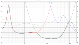
I had another quick look at the mid and I can improve the impedance to 4 Ohms by introducing an extra capacitor to the high pass part of the mid crossover. This has not sacrificed any sensitivity it has just reduced power lost in the crossover. keep in mind if you want high quality capacitors here they will be expensive you are often looking at $$$ for high value polypropylene. Eg. a 160uF polypropylene is $64 at Parts Express. The other option is to go for non polar electrolytic which would be much much cheaper but there might be some loss of fidelity at higher frequencies.
If 4 Ohm is high enough for your amplifier it should be OK to proceed, however there still might be a compromise over sensitivity as its likely that even with baffle loss the bass might need to be padded slightly to match the mid.
Are you happy to proceed on this basis?
I haven't included the baffle simulation yet so it will all need re-optimising once I have, that will take a while so if you don't want to proceed or you want to change mid now is the time to say.
Regards,
Andy
Attachments
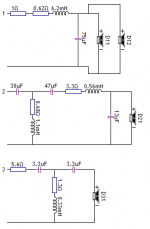
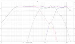
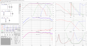
Midrange proved to cause impedance drops so this is as benign as I could do at the moment. Why is this 4 ohm unit designated as 8 ohm, who knows. FWIW, here is the design.
Is baffle step loss included here as well?
I had another quick look at the mid and I can improve the impedance to 4 Ohms by introducing an extra capacitor to the high pass part of the mid crossover. This has not sacrificed any sensitivity it has just reduced power lost in the crossover. keep in mind if you want high quality capacitors here they will be expensive you are often looking at $$$ for high value polypropylene. Eg. a 160uF polypropylene is $64 at Parts Express. The other option is to go for non polar electrolytic which would be much much cheaper but there might be some loss of fidelity at higher frequencies.
If 4 Ohm is high enough for your amplifier it should be OK to proceed, however there still might be a compromise over sensitivity as its likely that even with baffle loss the bass might need to be padded slightly to match the mid.
Are you happy to proceed on this basis?
I haven't included the baffle simulation yet so it will all need re-optimising once I have, that will take a while so if you don't want to proceed or you want to change mid now is the time to say.
Regards,
Andy
I dont want to change my midrange, can you please proceed with the design with out padding the woofer?
Sorry just read your message. If you already have the drivers I would suggest we move forward and you use electrolytic for the large mid range values. If you find there is any loss of fidelity you can always bypass with a small polypropylene.
I see Lojzek (I agree with him about impedance, this mid should definitely be called 6 ohm if not a 4 ohm as it is just under 6 for most of the operating region) has come up with a much higher sensitivity solution as well. I was struggling to smooth out the mid without some resistance. I will re-review.
Andy
Yes, the baffle step loss was included. I'd be temped to open up this midrange dome for it appears as if the chamber wasn't stuffed good enough, or perhaps I'm imagining. The calculation of a standing wave in reference to overall depth of 7.8 cm would show a resonance just above 2 kHz.
Yes, the baffle step loss was included. I'd be temped to open up this midrange dome for it appears as if the chamber wasn't stuffed good enough, or perhaps I'm imagining. The calculation of a standing wave in reference to overall depth of 7.8 cm would show a resonance just above 2 kHz.
How do i open up it up?
I am interested to know if you can fix that peak at 2KHz following Lojzek's advice.
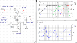
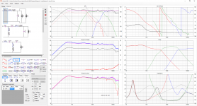
Anyway here is my effort at a design, good to see the bass is almost identical to Lojzek's. Hopefully this means the baffle simulation I used is valid.
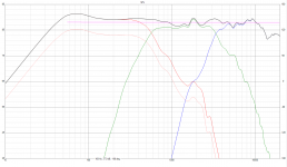
To avoid less than 4R over all impedance I used a bit of resistance in the mid range. This gives an approximate sensitivity of 88dB and I make the deviations on SPL +/- 1.5dB. The F3 point is around 35Hz.
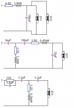
I have done two versions one which is +/- 1.5 across the whole range (This includes a 1R pad on the bass drivers) and one with no pad but the resistance loss of a cheapish inductor.
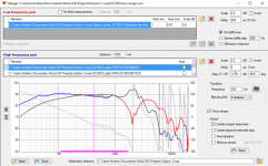
I have included close ups of the SPL and the impedance. To get the impedance to remain above 4R I had to compromise the phase a little its not completely in phase through the crossover. However the phase responses do track quite well through the crossover region so you should not get too much variation as you go off axis.
If you struggle to find any of the values let me know and I will see what the sensitivity is to the component. For instance I noticed after I had saved every thing that the 6.2mH inductor is not easy to get. I checked a 6.5mH I found at Parts Express with a slightly low resistance and it was fine the variation was small.
Anyway here is my effort at a design, good to see the bass is almost identical to Lojzek's. Hopefully this means the baffle simulation I used is valid.
To avoid less than 4R over all impedance I used a bit of resistance in the mid range. This gives an approximate sensitivity of 88dB and I make the deviations on SPL +/- 1.5dB. The F3 point is around 35Hz.
I have done two versions one which is +/- 1.5 across the whole range (This includes a 1R pad on the bass drivers) and one with no pad but the resistance loss of a cheapish inductor.
I have included close ups of the SPL and the impedance. To get the impedance to remain above 4R I had to compromise the phase a little its not completely in phase through the crossover. However the phase responses do track quite well through the crossover region so you should not get too much variation as you go off axis.
If you struggle to find any of the values let me know and I will see what the sensitivity is to the component. For instance I noticed after I had saved every thing that the 6.2mH inductor is not easy to get. I checked a 6.5mH I found at Parts Express with a slightly low resistance and it was fine the variation was small.
Attachments
In theory yes, however if they are close to each other they might couple and you would then get increased and unknown inductance. So if you plan to do this put them so that the cores of the inductors are at right angles to each other this minimises the field interaction and try to get some space between them. This is true for all the other inductors in the design as well try to keep them at right angles and as far apart as possible. The capacitors and resistors can go next to each other there is very little interaction between them.
I have managed to keep the impedance just over 4 Ohms across the whole frequency range. However basically you are right if there is a small frequency range dip below 3 ohms it should be OK. The higher in frequency that it occurs the less likely that it will cause a significant problem as most of the power in an audio signal is at low frequencies.
Frankly, I have never tried opening one as the Dynaudio's I own do not show any such anomalies and the Dayton's appear as if these were a knock-off's. I was thinking out loud when mentioning this FR issue. The greatest challenge is to arrive at a functioning crossover filter.
- Status
- This old topic is closed. If you want to reopen this topic, contact a moderator using the "Report Post" button.
- Home
- Loudspeakers
- Multi-Way
- need help designing a 3-way crossover