I assume it's an angle measurement, not pure port measurement. You are right though. But that also suggests the measurement distance was too close. There should be several different angle measurements to be a foundation for such a decision. Anyway, he is absolutely convinced he got the perfect measurements and solution, arguing or presenting different facts won't convince him. I won't press that any further, he won't believe it anyway.
Guys, did you ever measure something, or just speak the plain theory?
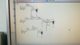
Look at what akabak predicts about that:
Look at what akabak predicts about that:
Attachments


Last edited:
From the measurements I've made in the past, I have selected a few that can prove the same behavior for the different positions of the resonator.
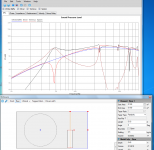
Following the experiments I made, I came to the conclusion that is synthesized in the EAW rl15 picture. If you have something to say or show, to deny this conclusion, I am open to discuss it.
Following the experiments I made, I came to the conclusion that is synthesized in the EAW rl15 picture. If you have something to say or show, to deny this conclusion, I am open to discuss it.
Attachments

Last edited:
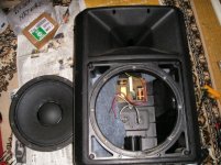
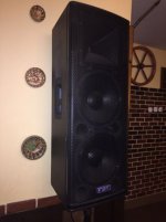
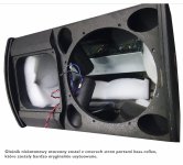
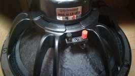
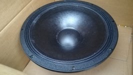
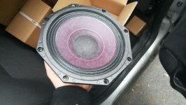
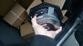
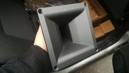
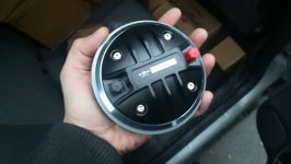
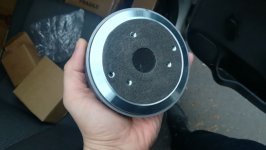
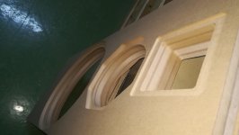
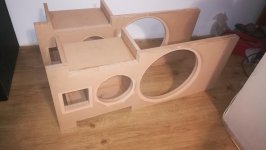
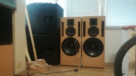
The drivers have arrived today.
Attachments
-
 WhatsApp Image 2018-02-20 at 15.34.43.jpeg143.7 KB · Views: 179
 -
 WhatsApp Image 2018-02-20 at 16.35.25 (3).jpeg169.3 KB · Views: 179
 -
 WhatsApp Image 2018-02-20 at 16.35.25 (1).jpeg136 KB · Views: 168
 -
 WhatsApp Image 2018-02-20 at 16.35.25 (2).jpeg102.5 KB · Views: 163
 -
 WhatsApp Image 2018-02-20 at 16.35.25.jpeg114.1 KB · Views: 171
 -
 WhatsApp Image 2018-02-20 at 16.35.26.jpeg90.3 KB · Views: 161
 -
 WhatsApp Image 2018-02-20 at 16.35.24.jpeg116.5 KB · Views: 157
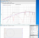
A simulation software is great, especially with predicting frequencies of peaks and dips, but it constantly overestimates amplitude of peaks.Guys, did you ever measure something, or just speak the plain theory?
Look at what akabak predicts about that:
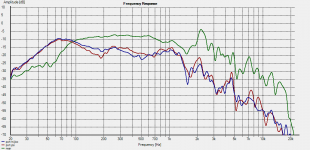
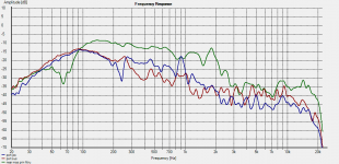
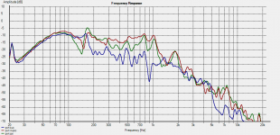
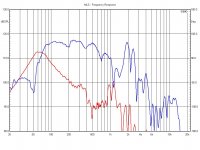
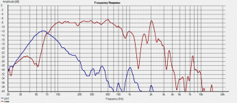
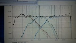
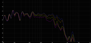
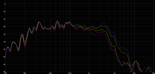
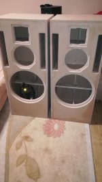
Different positions of port make different frequency response, of course. But there is a very thick line between bad and good vented enclosure. Here are two of my designs with pro 15" woofers. On the left is B&C 15NDL76, on the right is PAudio E15LF.From the measurements I've made in the past, I have selected a few that can prove the same behavior for the different positions of the resonator.
Compare the port output with your designs.
Attachments
Last edited:
Guys, did you ever measure something, or just speak the plain theory?
Thank you for the simulations and measurements but I was talking about the influence of such a huge port right beside the midrange because of the much, much narrower baffle and the baffle step being much higher.
The 3rd box looks like an older Monacor.
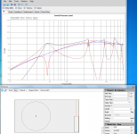
Different positions of port make different frequency response, of course. But there is a very thick line between bad and good vented enclosure. Here are two of my designs with pro 15" woofers. On the left is B&C 15NDL76, on the right is PAudio E15LF.
Compare the port output with your designs.
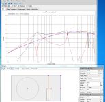
It also matters the port surface, but also the volume of stuffing in the box (and it's good to be zero to see the resonances of the enclosure). We must also be careful on the scale at which the measurements are presented.
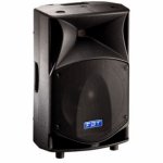
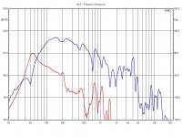
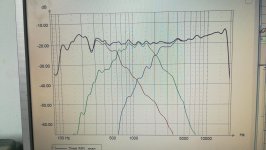
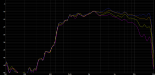
Here's an example of a box, Yamaha dsr115, with a much smaller port area. Do you think this makes a better box? It's all about compromises.
Attachments
Last edited:
Thank you for the simulations and measurements but I was talking about the influence of such a huge port right beside the midrange because of the much, much narrower baffle and the baffle step being much higher.
The 3rd box looks like an older Monacor.
I agree that there will be some shortcomings related to the baffle step or even the diffraction resulting from the air that comes out of the way through the ports.
But we must think that there are even more unfortunate cases, such as coaxial speakers, with horns played by the cone.
The measurements are from the following speakers: fbt verve212, fbt promaxx14, electrovoice sx300 and one no-name plastic enclosure with 4 ports. The last picture is eaw rl 15.
Last edited:
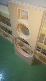

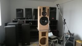
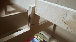
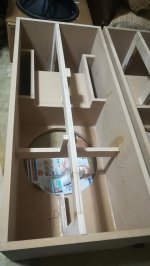
Last week i made some progress.
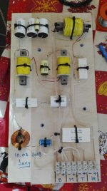
The back of the enclosure was glued and with some help from a friend i made the crossover. I keept some distance between the components for easy modifications.
The back of the enclosure was glued and with some help from a friend i made the crossover. I keept some distance between the components for easy modifications.
Attachments

Hi Mannien, thank you for you info. I am using it to 1700Hz, crossed 12 order acoutics, that means with only a capacitor in series and the rest is the driver own rule-off. That seems to be to much to ask? Even if padded 25 db down to meet a Hifi 8" woofer. It seems harsh in the 7-9KHz range. (I can find out of that with my eq) But maybe it is because of what happens lower in frequence. What horn do you use?
- Home
- Loudspeakers
- Multi-Way
- 15 Inch 3 way