Hi Gentlemen,
First I had better clear up some confusion.
I received any email from dyiaudio saying my posts were going to placed "under moderation",
I now realize that was just a standard "welcoming email" that perhaps arrived a little late and I took that completely the wrong way So my apologizes to all.
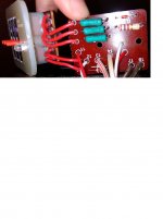
Anyway moving on, I have installed three new capacitors on each crossover, replacing the
47uf electrolytics with a polypropylene foil and the two 330uF electrolytics with new ones.
The sound has changed, remarkably, it is much more pleasant to listen to, all the harshness has gone thanks to everyone for their help with that.
I still think there is a lot of improvements to be done yet, so I have been
investigating further.
On taking Mooly`s advice, I have made a closer examination the attenuators they appear to be mostly non linear when testing with an ohm meter.
As a rough estimate they measure from about 0.5 to 4.3 ohms, but they are all over the place generally.
I am quite happy to add bypass resistors to the circuit, but with my little knowledge of electronics I am having trouble working out what values to use so I am hoping you kind gentlemen
can give me a starting point. I tried playing with the online calculator but really not sure what I am doing with the inputs
I realize this will take some experimenting but that is fine with me, resistors being cheap.
There are two attenuators one for the tweeter and one on the midrange.
The tweeters and mids are both 6 ohms measured across the terminals.
I think the bass speaker is 8 ohms.
The whole speaker is rated at 8 ohms 100W DIN
First I had better clear up some confusion.
I received any email from dyiaudio saying my posts were going to placed "under moderation",
I now realize that was just a standard "welcoming email" that perhaps arrived a little late and I took that completely the wrong way
So my apologizes to all.Anyway moving on, I have installed three new capacitors on each crossover, replacing the
47uf electrolytics with a polypropylene foil and the two 330uF electrolytics with new ones.
The sound has changed, remarkably, it is much more pleasant to listen to, all the harshness has gone
thanks to everyone for their help with that.I still think there is a lot of improvements to be done yet, so I have been
investigating further.
On taking Mooly`s advice, I have made a closer examination the attenuators they appear to be mostly non linear when testing with an ohm meter.
As a rough estimate they measure from about 0.5 to 4.3 ohms, but they are all over the place generally.
I am quite happy to add bypass resistors to the circuit, but with my little knowledge of electronics I am having trouble working out what values to use
so I am hoping you kind gentlemen can give me a starting point. I tried playing with the online calculator but really not sure what I am doing with the inputs
I realize this will take some experimenting but that is fine with me, resistors being cheap.
There are two attenuators one for the tweeter and one on the midrange.
The tweeters and mids are both 6 ohms measured across the terminals.
I think the bass speaker is 8 ohms.
The whole speaker is rated at 8 ohms 100W DIN
Attachments
![IMG_20180206_221400[1].jpg](/community/data/attachments/603/603587-7be51c5cfa4b48b1e8c41a7812b61373.jpg)
The email thing sounds very weird tbh. You would have had to receive an initial email when you signed up (that has a link to click to validate the account) but as far as I know that's it...
No idea
The variable controls are configured to try and maintain a constant impedance as they are rotated... as one side goes up in value then the other side goes down.
The only advice I could really give for those would be to initially give them a severe to and froing several times to temporarily clean them up.
Now set them to your preferred listening position and mark the position for reference.
Next disconnect one wire to the mid and tweeter to isolate them.
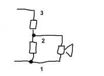
We now have to derive the pot values you are using.
1/ Remove (lift one end) of L3 and L4. This breaks any DC path that will interfere with readings.
2/ Measure from point 3 to point 1 for both pots and note the values. You may have to really press the probes into any connections in order to get a reliable low resistance contact.
3/ Now measure from point 1 to point 2 for both and note the values.
4/ Do the same between points 2 and 3 for both.
If you now add the readings for each pot you get the same value as you measured in step 2. That is a confirmation that nothing went astray.
You now have the two series resistor values needed to replace each pot with fixed values.
No idea
The variable controls are configured to try and maintain a constant impedance as they are rotated... as one side goes up in value then the other side goes down.
The only advice I could really give for those would be to initially give them a severe to and froing several times to temporarily clean them up.
Now set them to your preferred listening position and mark the position for reference.
Next disconnect one wire to the mid and tweeter to isolate them.
We now have to derive the pot values you are using.
1/ Remove (lift one end) of L3 and L4. This breaks any DC path that will interfere with readings.
2/ Measure from point 3 to point 1 for both pots and note the values. You may have to really press the probes into any connections in order to get a reliable low resistance contact.
3/ Now measure from point 1 to point 2 for both and note the values.
4/ Do the same between points 2 and 3 for both.
If you now add the readings for each pot you get the same value as you measured in step 2. That is a confirmation that nothing went astray.
You now have the two series resistor values needed to replace each pot with fixed values.
Yeah, that's properly the definition of an L-pad.The variable controls are configured to try and maintain a constant impedance as they are rotated... as one side goes up in value then the other side goes down.
Otherwise, it's a rheostat ( a potentiometer )
So, when in central position the situation should be "flat".
Moving the cursor you'll get a tilt or a lowering in volume of the component.
So in the "0" position there's already a resistor in series with the driver.
I said to completely remove them 'cos they are mechanically attached to the baffle where the drivers are. Another situation is when they are isolated from the speaker/enclosure chassis. Also the "contact" matter should be taken into consideration ( as...the less the better ).
The tweeters and mids are both 6 ohms measured across the terminals.
I think the bass speaker is 8 ohms.
You measured resistance ( R )
What is reported under " impedance" ( Z ) is...impedance !
Ohm is the same but one is electrical and DC the other refers to dynamic response since a speaker works in AC and it ( Z ) varies with frequency.
It's called nominal impedance, indeed.
Than you both very much, I noticed the value of one side of the L-pad increasing as the other decreased generally.
Next I will repeat the tests without the crossover connected.
"You now have the two series resistor values needed to replace each pot with fixed values"
Not 100% on what you saying here Mooly do I just need one resistor in parallel with the speaker the same value as across 1 and 3
or do I need one in series and one in parallel as the L-pad calculator depicts. Noting there is already
resistors in series in both circuits.
Yes pico I have read there is a difference between R and Z but the resistance is all I can measure with my meter, one day all this will be understood by me, I hope
Next I will repeat the tests without the crossover connected.
"You now have the two series resistor values needed to replace each pot with fixed values"
Not 100% on what you saying here Mooly
do I just need one resistor in parallel with the speaker the same value as across 1 and 3 or do I need one in series and one in parallel as the L-pad calculator depicts. Noting there is already
resistors in series in both circuits.
Yes pico I have read there is a difference between R and Z but the resistance is all I can measure with my meter, one day all this will be understood by me, I hope
Well that gives completely different readings with the crossover disconnected, thanks for picking that up Mooly.
The figures add up to within .1 of an ohm in most cases.
The dial on the tweeter is numbered from +3 to -7 The ohms range from 27 to 8
Zero (normal range) reads 20 -21 ohms
The dial on the midrange is numbered from +2 to -8 the ohms range from 22 to 8.5
Zero (normal range) reads 19 to 21 ohms
So I think I have got it now I just need to put resistors, close to the normal values
across 3 to 1 ie in parallel with the speaker?
Am I on the right path now gentlemen?
The figures add up to within .1 of an ohm in most cases.
The dial on the tweeter is numbered from +3 to -7 The ohms range from 27 to 8
Zero (normal range) reads 20 -21 ohms
The dial on the midrange is numbered from +2 to -8 the ohms range from 22 to 8.5
Zero (normal range) reads 19 to 21 ohms
So I think I have got it now
I just need to put resistors, close to the normal valuesacross 3 to 1 ie in parallel with the speaker?
Am I on the right path now gentlemen?
The speaker should go to the junction of two series resistors, the value of the 'top' resistor being the value you measure between points 2 and 3, and the value of the bottom resistor the value you measure between points 2 and 1.
You can only measure between those points once the other DC paths are removed (the speaker and the coil).
You can only measure between those points once the other DC paths are removed (the speaker and the coil).
Attachments
Changed the resistors today twice, first tryout to theoretical values sounded very flat and muffled so dropped 1.03 ohm on the #3 cap on the tweeter and 1.2 ohm on the #3on the midrange, better but nothing like yesterday which was quite good in comparison, love those tweeters .
I think it might be a problem with the amp, the over load light on the speakers are still flashing although probably up a notch higher 5 I never had them flashing on my exact same system when it was new used to occasionally be on 8
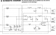
Thinking I need to sort the amp out first, been studying the schematic
.I think it might be a problem with the amp, the over load light on the speakers are still flashing although probably up a notch higher 5
I never had them flashing on my exact same system when it was new used to occasionally be on 8 Thinking I need to sort the amp out first, been studying the schematic
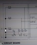
The LED on the speaker appears to be a simple indicator with a discrete AND gate logic arrangement, although part of it doesn't look right tbh.
The three drivers are fused, so all good there.
The output side of each fuse goes via a 2k7 into the LED. There is a reverse biased diode for polarity protection for the LED and also a zener and resistor for overvolts.
The rest of the connections don't make sense tbh. Is it like this ?
The three drivers are fused, so all good there.
The output side of each fuse goes via a 2k7 into the LED. There is a reverse biased diode for polarity protection for the LED and also a zener and resistor for overvolts.
The rest of the connections don't make sense tbh. Is it like this ?
Attachments
Thanks very much Mooly you are a champion
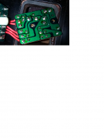
I have not had that board out so no idea, something to look at tomorrow. Although the light blinks none of the overloads trip. I always back it off as soon as I see it happening, not so sure the previous owner new what was happening was doing it with his amp as well.
It does not play anywhere as loud as my old system that is why I was thinking the amp may be struggling to put out a good signal it does not have much spacial effect ether all seems to be on the one plane if you know what I mean?
I should say I am now playing music off the computer where as I had a SL10 turntable with one of those moving coil pickups so I guess that is a bit like comparing apples with whatever... sorry not sure why the italics is on
Well that LED shown on the speaker crossover simply responds to the voltage applied to the input.
Now this will be an old LED and as such far less efficient than modern examples. Lets say it needs 3 milliamps to be bright and that it drops say 2 volts. That means we need to see 3ma in the series resistors, and which are effectively all in parallel giving the equivalent of 900 ohms.
So we need 4.7 volts applied to the input to do that, and that voltage can be DC or peak value AC to light the LED. 4.7 volts peak is just the equivalent of 1.3 watts RMS into 8 ohms.
So the LED will light at relatively small input voltages.
Perceived loudness has a lot to do with the basic efficiency of a speaker.
How much headroom is needed
You can also determine the impedance of a speaker from this method:
"The Dynamical Loudspeaker Impedance"?
How much headroom is needed
You can also determine the impedance of a speaker from this method:
"The Dynamical Loudspeaker Impedance"?
![IMG_20180206_221411[1].jpg](/community/data/attachments/607/607482-3695b6f4926d80c01240e70b3f3667f9.jpg)
The board layout shows something different again... which is that there is a missing connection on the circuit diagram but and so the LED is effectively across the incoming audio feed but now with a series zener and resistor. So the LED will not light until the zener voltage PLUS the LED voltage is exceeded.
The three 2k7 resistors modify that behaviour in the event of a fuse/trip opening.
Although I have never had cause to do this, I think white noise (hiss) would be a good method of phasing the tweeter and midrange. I would guess the sound would be 'smoothest' when correctly phased... but as I say, I've never tried. You should be able to phase left and right that way.
I wonder how good the contacts are in those overload breakers ? These days I think it would be pretty much unheard of to add something like that to a 'hifi' design.
I am wondering whether they would be better either linked out, or if you still want protection then replaced with solderable fuses such as 'Wickmans'.
I am wondering whether they would be better either linked out, or if you still want protection then replaced with solderable fuses such as 'Wickmans'.
Yes, well they have not tripped out yet, and perhaps the lights are giving a false indication, the speakers and amp seem to be acting OK when they start flashing.
I will look into the Wickmans, Great thinking Mooly Thanks that should cover both bases. I would feel much happier knowing they were protected hard to get replacements these days.
I will look into the Wickmans, Great thinking Mooly Thanks
that should cover both bases. I would feel much happier knowing they were protected hard to get replacements these days.Flashing lights were all part and parcel of equipment of that era. I'll recalculate the voltage the LED will light at later based on how we now know the circuit to be. Those 2k7 are in parallel with the LED, but if a trip operates then the LED will light earlier (as in needing less input voltage).
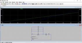
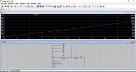
Here you go. A quick simulation shows graphically how it works. The input voltage is rising with time (this is a DC voltage) and the LED begins to conduct at around 18 volts.
If we trip all three breakers then it conducts at around 13 volts.
Voltage is on the left and current on the right.
So for an AC music signal the conduction points represent the peak of the AC voltage and you have to remember that a quick transient will not be very visible.
18 volts peak would be 20 watts equivalent into 8 ohms.
Attachments
- Home
- Loudspeakers
- Multi-Way
- Technics SB-10 Crossover Questions