Hi jReave & Tony,
Thanks so much for your detailed explanations! I'm confident that I can proceed and get some decent measurements to evaluate with the direction you have provided. I might be in a slight holding pattern until my shipment of new midranges come in. The Dayton RS150P mid woofers were not working out very well for me so I decided to order SB Acoustics 15MFC30-8 poly cones as a suitable replacement. So, I'll be waiting on those to drop into the 3 ways before proceeding with measurements. In the mean time, another project is waiting in the wings. This one is a standmount 2 way with Peerless 830869 8 inch woofers and waveguide mounted Scanspeak D2604/83300 tweeters. I just ordered a longer usb cable for my Umik1 mic and it should probably arrive mid week. This will allow me to set up my work station further away from mic stand and yield cleaner measurements (hopefully). I will post measurements of the 2 way standmount for guys to critique if you don't mind. This may be a better strategy anyways to gain more experience before taking on the 3 ways.
Best Regards,
Rich
Thanks so much for your detailed explanations! I'm confident that I can proceed and get some decent measurements to evaluate with the direction you have provided.
I might be in a slight holding pattern until my shipment of new midranges come in. The Dayton RS150P mid woofers were not working out very well for me so I decided to order SB Acoustics 15MFC30-8 poly cones as a suitable replacement. So, I'll be waiting on those to drop into the 3 ways before proceeding with measurements. In the mean time, another project is waiting in the wings. This one is a standmount 2 way with Peerless 830869 8 inch woofers and waveguide mounted Scanspeak D2604/83300 tweeters. I just ordered a longer usb cable for my Umik1 mic and it should probably arrive mid week. This will allow me to set up my work station further away from mic stand and yield cleaner measurements (hopefully). I will post measurements of the 2 way standmount for guys to critique if you don't mind. This may be a better strategy anyways to gain more experience before taking on the 3 ways.Best Regards,
Rich
Hello Guys,
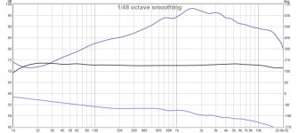
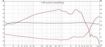
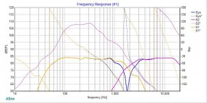
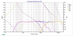
I'm back again with some more measurements to look over and let me know what you think. These are a 2 way standmount speakers with Peerless 830869 8" woofer mounted above SS D2604/83300 tweeter in a Monacor WG300. The inspiration for this design came from Troel Gravesen's 8008-Corner for near wall placement. Hopefully, going down a slightly different design path does not blow up in my face.
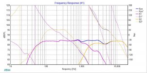
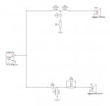
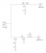
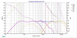
I have also attached a preliminary Xover schematic. Its obvious that the dip around 5k is going to be the challenge. I'm not sure how to go about smoothing that region. The raw tweeter response looks rather nice so I don't know why things get wonky once the filter is dropped in. Anyways, as always help is much appreciated!
Best Regards,
Rich
I'm back again with some more measurements to look over and let me know what you think.
These are a 2 way standmount speakers with Peerless 830869 8" woofer mounted above SS D2604/83300 tweeter in a Monacor WG300. The inspiration for this design came from Troel Gravesen's 8008-Corner for near wall placement. Hopefully, going down a slightly different design path does not blow up in my face.I have also attached a preliminary Xover schematic. Its obvious that the dip around 5k is going to be the challenge. I'm not sure how to go about smoothing that region. The raw tweeter response looks rather nice so I don't know why things get wonky once the filter is dropped in. Anyways, as always help is much appreciated!
Best Regards,
Rich
Attachments
-
 standmount-XOVER.jpg31.8 KB · Views: 145
 -
 peerless830869_port-nearfield.jpg71.3 KB · Views: 54
 -
 peerless830869_nearfield.jpg72.2 KB · Views: 56
 -
 Peerless830869+SSd2604-83300_FR.jpg63.9 KB · Views: 49
 -
 Peerless830869_FR+phase.jpg68.7 KB · Views: 58
 -
 SSd2604-83300WG_FR+phase.jpg66.5 KB · Views: 143
 -
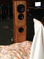 IMG_0487.jpg405.8 KB · Views: 137
 -
 standmount-FR-drivers.jpg84.9 KB · Views: 140
 -
 standmount-FR.jpg96.9 KB · Views: 136
Very quick comments based on first glance
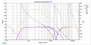
Looks like you are factoring in full baffle step, which almost certainly will result in very heavy bass if you are planning on putting these close to the wall. Also I'm a bit surprised at your woofers response curve, I'd have expected an 8" ported to be going much lower, it seems to roll off way too quickly, even with baffle step I would not expect that.
There is definitely something wonky with your tweeter circuit. I'd try getting rid of the lpad initially maybe use say a 3.3 or 4.6uf cap as the first cap just by itself and see what that does to the response. add in a coil maybe between say 500 - 800uH and see how that looks. Iterate until you get what you want.
You should be able to get that hump down without the dip at 5Khz, you want a nice rolloff on the tweeter, try putting in some target response curves in. It looks like you have gone for an approx 1.8Khz crossover point, so you could say put in 1.8Khz 4th order LR target curves and then try to get the response of the drivers to conform to those curves.
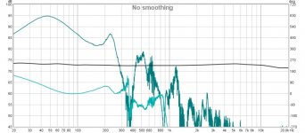
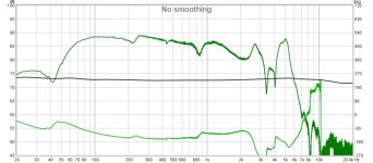
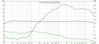
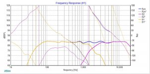
Actually looking again at your measurements, the 2nd last one looks much more like what I'd expect for the woofer, is that a nearfield measurement (I assume the last is the port nearfield? The peak at 5Khz on the woofer would almost certainly benefit from a notch filter, and that may be partially responsible for your suck out at 5khz.
Tony.
Looks like you are factoring in full baffle step, which almost certainly will result in very heavy bass if you are planning on putting these close to the wall. Also I'm a bit surprised at your woofers response curve, I'd have expected an 8" ported to be going much lower, it seems to roll off way too quickly, even with baffle step I would not expect that.
There is definitely something wonky with your tweeter circuit. I'd try getting rid of the lpad initially maybe use say a 3.3 or 4.6uf cap as the first cap just by itself and see what that does to the response. add in a coil maybe between say 500 - 800uH and see how that looks. Iterate until you get what you want.
You should be able to get that hump down without the dip at 5Khz, you want a nice rolloff on the tweeter, try putting in some target response curves in. It looks like you have gone for an approx 1.8Khz crossover point, so you could say put in 1.8Khz 4th order LR target curves and then try to get the response of the drivers to conform to those curves.
Actually looking again at your measurements, the 2nd last one looks much more like what I'd expect for the woofer, is that a nearfield measurement (I assume the last is the port nearfield? The peak at 5Khz on the woofer would almost certainly benefit from a notch filter, and that may be partially responsible for your suck out at 5khz.
Tony.
Last edited:
Hi Tony,
Thanks for taking the time to share your thoughts! Yes, the second to last measurement is the woofer nearfield FR and last is indeed the port nearfield. Concerning baffle step, I was going on jReave's recommendation to start with full 6db and adjust after voicing if bass is to heavy (maybe I misunderstood).
I will start my design work in PCD7 so target curves can be added. In my latest Xover version, I did eliminate the Lpad and that did help. But, more tweaking is required to smooth it out more. Back to the drawing board I go.
Best,
Rich
Thanks for taking the time to share your thoughts!
Yes, the second to last measurement is the woofer nearfield FR and last is indeed the port nearfield. Concerning baffle step, I was going on jReave's recommendation to start with full 6db and adjust after voicing if bass is to heavy (maybe I misunderstood).I will start my design work in PCD7 so target curves can be added. In my latest Xover version, I did eliminate the Lpad and that did help. But, more tweaking is required to smooth it out more. Back to the drawing board I go.
Best,
Rich
Hi Tony,
Thanks for taking a look at that and commenting! After taking a closer look at the frequency response in the low bass region; I have a felling jReave might have me lower that to achieve a better F3. I'm pretty sure it would require a shunt notch filter but not quite positive. Tomorrow, I will try and see what might work to get F3 around 46 hz.
Best Regards,
Rich
Thanks for taking a look at that and commenting!
After taking a closer look at the frequency response in the low bass region; I have a felling jReave might have me lower that to achieve a better F3. I'm pretty sure it would require a shunt notch filter but not quite positive. Tomorrow, I will try and see what might work to get F3 around 46 hz.Best Regards,
Rich
Just remember that anything you do to improve the really low bass (through passive crossover means) is going to reduce your overall efficiency Port tuning may be a more productive avenue.....
Looking at your rolloff it does seem (even with the spliced nearfield) to be quite high for an 8" ported system.
Tony.
Port tuning may be a more productive avenue..... Looking at your rolloff it does seem (even with the spliced nearfield) to be quite high for an 8" ported system.
Tony.
Just quickly because I won't have more time 'til later:
- the 2nd xo looks much better. Elegant.
- I'm thinking the lack of LF is a simulation problem. The low end in the xo sim and the low end from your NF measurement are almost identical. It looks therefore like there is no discernible addition from the port in the sim even though your measurement shows it to be there. So don't worry about it?
- Notice I said start with 6dB of baffle step if you are placing the speakers reasonable distances away from boundaries. Up against a wall (or 2) would change that.
- You can use target filters in XSim, it just requires a little more work in that you have to create them and then import them. I use JB's Response Modeler's HP and LP sections near the top left of the program. Create the curves and save them. Then create new drivers in XSim that are not wired up to anything and import the files as your target curves. Very simple really.
Thanks Tony,
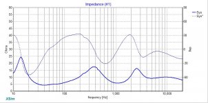
You are correct. I believe port tuning is a little higher then expected. My target based on simulations in Unibox and Winisd Pro was 38 Hz. In looking at actual z and nearfield measurements, it looks to be 41 Hz. tuning. If required to obtain the right bass level I can always extend the tube some to lower the tuning point. The boxes are rather deep so there is some room to extend before being to close to the front wall. Even then, I suppose its not against the law to elbow up if need be.
Best Regards,
Rich
Hello Guys,
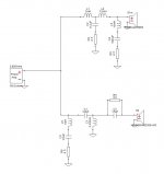
Back once again with another Xover design for consideration. This design is an attempt to address resonant peaks and possible offer better bass extension. The cost as mentioned prior in this thread is reduced overall system sensitivity. I'm learning (in my still newbie state) that compromises are inevitable. With that said, I'm leaning slightly toward the version posted here for a few reasons.
1. Even though the parts count is higher; I already have most all the components so cost will be less then the simple version. Got to like that.
2. Would seem to offer better load presented to the amplifier. Not sure if it is a big consideration but could not hurt either.
3. Rather not have to add a subwoofer if system is bass shy. So achieving the lowest F3 is a design goal.
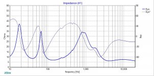
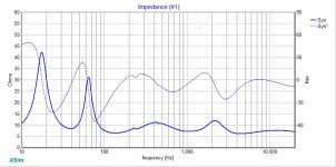
What are your guys thoughts? BTW, the last photo is system z and phase of the simple version for comparison.
Best,
Rich
Back once again with another Xover design for consideration.
This design is an attempt to address resonant peaks and possible offer better bass extension. The cost as mentioned prior in this thread is reduced overall system sensitivity. I'm learning (in my still newbie state) that compromises are inevitable. With that said, I'm leaning slightly toward the version posted here for a few reasons.1. Even though the parts count is higher; I already have most all the components so cost will be less then the simple version. Got to like that.
2. Would seem to offer better load presented to the amplifier. Not sure if it is a big consideration but could not hurt either.
3. Rather not have to add a subwoofer if system is bass shy. So achieving the lowest F3 is a design goal.
What are your guys thoughts? BTW, the last photo is system z and phase of the simple version for comparison.
Best,
Rich
Attachments
Hi jReave,
My sincere apologies. I somehow missed your last post. Unless you feel differently; I'm going to stay with the 6 db of baffle step that was modeled in Response Blender. Unless I'm overlooking something, that program can only display a full baffle step loss. My work around has been to use Response Modeler and apply a given baffle step percentage after splicing in nearfield/farfield data in Response Blender. There probably is a smoother method that I'm not aware of at this point.
These speakers are going in my offfice/exercise room which is rather smallish in size. Speakers will be 4.5 feet from side walls and 28 inches from rear wall to front of speaker. The back of speakers will be 12 inches from rear wall. Given this added information, do you think I should re-visit my 30 or so Xover versions? Like I said, to much time on my hands. The fun soon ends though. I return back to work in less then two weeks.
Thanks in Advance,
Rich
My sincere apologies. I somehow missed your last post.
Unless you feel differently; I'm going to stay with the 6 db of baffle step that was modeled in Response Blender. Unless I'm overlooking something, that program can only display a full baffle step loss. My work around has been to use Response Modeler and apply a given baffle step percentage after splicing in nearfield/farfield data in Response Blender. There probably is a smoother method that I'm not aware of at this point. These speakers are going in my offfice/exercise room which is rather smallish in size. Speakers will be 4.5 feet from side walls and 28 inches from rear wall to front of speaker. The back of speakers will be 12 inches from rear wall. Given this added information, do you think I should re-visit my 30 or so Xover versions?
Like I said, to much time on my hands. The fun soon ends though. I return back to work in less then two weeks. Thanks in Advance,
Rich
Have only had a quick look. I've not used impedance flattening before so cannot comment from experience, so won't venture an opinion, other than 500uf is a big cap
When we talk about the Baffle step, it's correct to put the full baffle step into the measurements when you do the blending, it's just when you do the crossover modeling you don't necessarily want to set your target so that it is flat down to the low bass.
I find that a bit of a challenge because your natural tendency is to try and get a nice flat response. If you set your target response curves say for instance 3db higher and then don't worry about the low end, you should be ok.
Tony.
Hi Tony,
Thanks for once again for sharing your thoughts. Just to make sure I'm following you correctly, the Xover version from post #65 would that meet the target response curve that you are after? Or should I pad down the HF region a db or 2? I have noticed from studying the work of Troels Gravesen, that he likes to have about 2-3 db downward tilt to the response curve. My only uncertainty is does the response curve change much as the listening distance becomes further away then the modeled design. For instance, I took these measurements at 27 inches and based the the Xover schematic in Xsim off that same mic distance. Does the response curve begin to droop some as distances expand (say to 6-7 feet)? My tendency has been to target as flat as possible thinking that by the time sound reached the listening position that the highs would be falling off some.
Thanks in Advance,
Rich
Thanks for once again for sharing your thoughts.
Just to make sure I'm following you correctly, the Xover version from post #65 would that meet the target response curve that you are after? Or should I pad down the HF region a db or 2? I have noticed from studying the work of Troels Gravesen, that he likes to have about 2-3 db downward tilt to the response curve. My only uncertainty is does the response curve change much as the listening distance becomes further away then the modeled design. For instance, I took these measurements at 27 inches and based the the Xover schematic in Xsim off that same mic distance. Does the response curve begin to droop some as distances expand (say to 6-7 feet)? My tendency has been to target as flat as possible thinking that by the time sound reached the listening position that the highs would be falling off some. Thanks in Advance,
Rich
OK I would say that your target response curve in post 65 was probably around 84db, what I'm saying is make it instead maybe 87db (that's half way between full baffle step compensation and no baffle step compensation).
You will see that your lower frequencies don't seem to be very flat (in the sim), but that will hopefully be evened out by the re-inforcement you get being close to the wall.
On the question of down tilting response, that is a tricky one, because it will be very room dependent as well as personal preference dependent.
If you have a very lively room (lots of hard surfaces) then you probably want the downward tilt, if you have a pretty dead room, then flatter will probably be better.
It also depends on your subjective preferences for treble. What you will find is than in a typical room you will naturally get a falling response as frequency increases. My own speakers I went with pretty flat and I've been happy with that. I have carpeted floor, and curtains on the back wall, and a fair bit of furniture in the room, so it is on the more dead side.
There are different schools of thought on this. Some say tune the crossover to the room, others say make the crossover flat for anechoic and eq for the room.
I made it flat for anechoic, and haven't found that I needed to eq (though I do have a hump that is due to having too much baffle step compensation factored in), but some people may not like my setup (generally it has received praise from anyone who has listened, but I haven't had any hard core audiophiles over )
Tony.
You will see that your lower frequencies don't seem to be very flat (in the sim), but that will hopefully be evened out by the re-inforcement you get being close to the wall.
On the question of down tilting response, that is a tricky one, because it will be very room dependent as well as personal preference dependent.
If you have a very lively room (lots of hard surfaces) then you probably want the downward tilt, if you have a pretty dead room, then flatter will probably be better.
It also depends on your subjective preferences for treble. What you will find is than in a typical room you will naturally get a falling response as frequency increases. My own speakers I went with pretty flat and I've been happy with that. I have carpeted floor, and curtains on the back wall, and a fair bit of furniture in the room, so it is on the more dead side.
There are different schools of thought on this. Some say tune the crossover to the room, others say make the crossover flat for anechoic and eq for the room.
I made it flat for anechoic, and haven't found that I needed to eq (though I do have a hump that is due to having too much baffle step compensation factored in), but some people may not like my setup (generally it has received praise from anyone who has listened, but I haven't had any hard core audiophiles over
) Tony.
Thanks Tony,
I understand what you mean now. Tomorrow, I will try to raise response curve 3 db as you suggested. Before proceeding with purchase of Xover components, I will post another version for critique. Everything you mentioned makes perfect sense. I really appreciate you taking the time to share your thoughts.
Best Regards,
Rich
I understand what you mean now. Tomorrow, I will try to raise response curve 3 db as you suggested. Before proceeding with purchase of Xover components, I will post another version for critique.
Everything you mentioned makes perfect sense. I really appreciate you taking the time to share your thoughts.Best Regards,
Rich
The other suggestion would be when you are purchasing, consider that you may decide you need to adjust, so don't go overboard I'm actually still using my axon caps that I bought for experimenting because they were very well priced. Some people say they don't like them, I've not felt the need to upgrade.
Tony.
I'm actually still using my axon caps that I bought for experimenting because they were very well priced. Some people say they don't like them, I've not felt the need to upgrade. Tony.
Hey Rich,
Ok, I've had a closer look at a few things. Here are my questions and comments:
Looking at your measurements in post #62, if you look at f3 in the NF and then f3 in your sim, both are at about 67Hz, which means that your sims haven't included the port output which is peaking at around 40Hz. In terms of the simulation accuracy, it's not a big deal because the port isn't affecting the 100 - 200Hz range and that's what you should be looking at to set your target xo levels. So, don't concern yourself with trying to milk more out of the LF because you don't see much in the sim - it doesn't look to me like an accurate representation of reality.
Now when I add in 6dB of baffle step to your NF and blend to your FF, I get a target level of about 84dB, which is exactly where you are in your sims on page 7. So, I'm saying discard your effort from post #72. Although using a resonance compensation filter on the woofer achieves what you were attempting (lowering f3), I think it's totally unnecessary (as explained above) and in fact I don't think I've ever seen it done on a 2-way before - the result is a serious loss in efficiency.
I must admit I am a bit confused by the level of your NF measurement in post #62. Typically when you go from measuring 2 or 3 ft away to a matter of 1/8" or 1/4" from the cone, you are going to see a considerable increase in SPL in the nearer measurement. In Jeff's white paper on the measurement process, there's a difference of 14.7dB, but when I tried blending your files, I needed to add .5dB to the NF to get the best blend with the FF (again, that's with the full 6dB of bsc). ?? I am thinking that you may have changed the amplifier level between measurements whereas it should be kept the same throughout.
Concerning baffle step, your distances to walls don't look too bad to me but a small room may add a little extra to the bass. You might try finding a corner in your present measurement room and set the speaker up with your intended setup distances and this time measure a few ft away with the gate wide open. This will give you a better idea of what you'll really be hearing in a room, although the effects of a small room won't be there.
The difficulty in this instance is understanding how to interpret it, because now you are no longer looking at an anechoic FR and so the target is no longer flat. What you'll be after on the high end is a diminishing curve more similar to the power response in PCD and on the low end, an increasing response due to the additions of the room and its boundaries. Look up House Curves to give you more insight. Or just to open up another can of worms.
Having said that, I would still probably start with the full baffle step and then when you get it in your real room, adjust either the xo or eq to taste. This will probably also apply to the HF level too - whether in room you want to make an adjustment there too and if you want to do it with the xo or eq.
However, this is really a sort of flip the coin scenario - it's just as valid to start with a little less bsc and then listen and adjust from there. It's just a case of adjusting either up or down. The only possible advantage to starting with more bsc is that to make the adjustments, you need inductors of lower value which you can do by unwinding the bigger ones you start with (measuring instrument required) whereas if you start with lower bsc and need to go bigger, you'll need buy new, bigger inductors.
Re bsc, both ways to sim it seem valid to me. You can add the full 6dB of loss and then set a target level above that as Tony suggests or you can adjust baffle loss in Response Modeler and then import that into Response Blender. Although you have to realize in the latter case that you will be blending a FF response with the full 6dB loss with a NF with only say, 3 or 4dB of loss. You may need to adjust that a little bit too.
So that leaves me with the xo sim you did in post #65. Simple and effective. I don't know what that woofer peak at about 3kHz is going to be like, but maybe, as Tony suggested before, you may want to tank that down with a simple capacitor in parallel with L1.
Let's see where those suggestions get you.
Thanks for the input guys,
I realized a mistake made in taking nearfield measurements. As jReave suspected, I had different Spl levels for near and farfield. So, the sims in this post will reflect the changes that were made to correct my rookie move.. I will also attach all my raw measurements so you guys can take a look if you like. I'm still finding it challenging to reach 87 db reference level even with factoring in 50 percent baffle step loss. Which by the way creates a wild sag in the lower mid range. The version posted here is with full baffle loss applied in Frequency Response Blender. I really appreciate the in depth and well thought out responses from you guys!
Best Regards,
Rich
I realized a mistake made in taking nearfield measurements. As jReave suspected, I had different Spl levels for near and farfield. So, the sims in this post will reflect the changes that were made to correct my rookie move.
. I will also attach all my raw measurements so you guys can take a look if you like. I'm still finding it challenging to reach 87 db reference level even with factoring in 50 percent baffle step loss. Which by the way creates a wild sag in the lower mid range. The version posted here is with full baffle loss applied in Frequency Response Blender. I really appreciate the in depth and well thought out responses from you guys! Best Regards,
Rich
Attachments
- Status
- This old topic is closed. If you want to reopen this topic, contact a moderator using the "Report Post" button.
- Home
- Loudspeakers
- Multi-Way
- Need help interpreting measurements