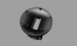
Your GRT-145 looks "ripe" for a larger waveguide/horn - with good extension and resulting higher efficiency, and very low resulting distortion. ..at that point you would seriously have to ask what a good treble compression driver was needed for. Hint.. Hint.. -this niche needs filling!")
Thanks!
Yes, of course, this issue deserves attention.
For starters, we are launching a shallow waveguide (like the RT850). The main task of this waveguide is the correction of the radiation diagram. It has a slight gain in the middle frequency region - only 3 dB.
There are thoughts about the development of a horn. But this task is in the more distant plans.
Attachments
There is no opportunity for a while...
Is it possible to measure the Dayton Audio RS270P-8A (or RS270P-4A)?
I notice that the TS parameters shown on many of the impedance frequency response sections (for example, the sb15nrxc30-8) disagree significantly with the manufacturer spec sheet.
A couple questions related to that:
1. What is your process for breaking in drivers before measuring them? In my own testing of the sb15nac30-8 (alum cone version of the above mentioned nrxc) I found thata vigorous break in process did significantly change my TS measurements with DATS2, although not enough that it matched the manufacturer specs still.
2. Would a greater degree of break in (if it affects TS params) result in changes to other measurements like SPL frequency response and distortion? Be interesting to test this.
3. Would you recommend designing based off of manufacturer specs or measured specs? I'm particularly curious about this one given that I suspect much of the difference between these, at least for my own measurements, is due to my not measuring properly/as well as the manufacturer.
I'm not an expert, but I remember this and I guess it is still relevant http://www.gr-research.com/burnin.htm
"As noted also the greatest amount of change will take place in the beginning of the burn in period and gradually gets less and less, finally reaching a point at which it stabilizes and shows little change at all from continued use. Most all manufacturers recommend 40 to 50 hours of burn in time to reach an acceptable level of stabilization."
"As noted also the greatest amount of change will take place in the beginning of the burn in period and gradually gets less and less, finally reaching a point at which it stabilizes and shows little change at all from continued use. Most all manufacturers recommend 40 to 50 hours of burn in time to reach an acceptable level of stabilization."
Thanks for sharing that Juhazi! It seems to suggest that measurements of spl frequency response and distortion ought to change with breakin, in addition to TS params. It also seems to suggest better results by using the manufacturer specs instead of measured specs since one would expect a manufacturer both knows what they are doing (better than me at least) and has a solid, rigorous measurement process.
Thanks again
Thanks again
I notice that the TS parameters shown on many of the impedance frequency response sections (for example, the sb15nrxc30-8) disagree significantly with the manufacturer spec sheet.
A couple questions related to that:
1. What is your process for breaking in drivers before measuring them? In my own testing of the sb15nac30-8 (alum cone version of the above mentioned nrxc) I found thata vigorous break in process did significantly change my TS measurements with DATS2, although not enough that it matched the manufacturer specs still.
2. Would a greater degree of break in (if it affects TS params) result in changes to other measurements like SPL frequency response and distortion? Be interesting to test this.
3. Would you recommend designing based off of manufacturer specs or measured specs? I'm particularly curious about this one given that I suspect much of the difference between these, at least for my own measurements, is due to my not measuring properly/as well as the manufacturer.
I give impedance curves not for the purpose extracting TS data from them but mostly to show up hidden resonances in the moving system. So I don't mind if TS parameters always match with ones from datasheet. This question gets my attention in a loudspeaker designing only.
1. Usually I break in a driver during 30 min by applying voltage at Fs and increasing its level until a mechanic noise appears.
2. The break in doesn't change the frequency response and doesn't change distortion at frequencies much higher than Fs. If it change distortion in vicinity of Fs it should be checked in nearest future on the example of SB17NBAC-35-8.
3.Sometimes I measure impedance for not broken-in drivers. The SBA drivers change theirs TS parameters very notably after a break in but it is not worth to worry about that because that changing has very small effect on designing the loudspeaker enclosure. To assess a loudspeaker enclosure you can use TS data for unbroken-in driver. But for the precise designing you should take TS data for the broken in driver.
Very good link
I'm not an expert, but I remember this and I guess it is still relevant http://www.gr-research.com/burnin.htm
-what the link fails to mention is the effect with excursion before and after sufficient break-in.
Compliance often drops (after break-in) with smaller ranges of excursion (..lower spl) depending on the driver's suspension.
If the Surround is a low-loss design/material, it factors very little with small ranges of excursion (though it does effect the driver in other respects). Instead the Spider dominates, and the Spider typically undergoes the most change - and may lower the compliance significantly near the driver's resting position.
Lower compliance with low excursion tends to reproduce better recorded depth of field effects (assuming the driver's motion is being limited).
Klippel has this sort of measurement display. S&L Woofer Tester Pro does as well.
The measurements of ScanSpeak 26W/4534G00 woofer have been added:
ScanSpeak 26W/4534G00 | HiFiCompass
ScanSpeak 26W/4534G00 | HiFiCompass
I'm agree, just the fantastic driver. Taking in account its price I don't know another driver that could concur with it.Wow! Golden samples?
-the best lower freq. distortion I've seen measured for this driver (..though I might have read the input level wrong and prior tests).
Very nice!
The both drivers from the pair were being measured equally well.
8- Ohm version 26W/8534 as good as 4-Ohm one, as I can remember.
The measurements of ScanSpeak 15M/4624G00 midrange have been added:
ScanSpeak 15M/4624G00 | HiFiCompass
ScanSpeak 15M/4624G00 | HiFiCompass
The measurements of ScanSpeak 18W/8531G00 woofer have been added:
ScanSpeak 18W/8531G00 | HiFiCompass
ScanSpeak 18W/8531G00 | HiFiCompass
What browser do you use?Your site does not work properly, the menu bar is broken
- Home
- Loudspeakers
- Multi-Way
- Some speaker driver measurements...