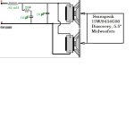
I am new to passive crossovers and have decided to model my crossover after a friend's. He has a pair of the best sounding speakers I have ever heard that he built in an MTM config using two 15W/8434G00 Discovery woofers and one Scanspeak R2604/832000 tweeter. He says they are crossed over at 3400Hz. The woofers are obviously running in parallel in his configuration. I will be using a box with about half the volume of his and it will be a two way with only one of these woofers, so the nominal ohm load should be 8 instead of 4. I can't figure out what the values should be for one woofer instead of two in parallel(in fact, I'm not even sure what all of these components do- I think part of it is a Zobel network?). I have attached the low pass crossover he used and would like to know what each of the values should be for me to use it in my configuration. I hope this makes sense. Any help would be greatly appreciated.
Attachments
Yes, 0.4 mH with wire >1mm ( diameter or area ) seems rather low for filtering a woofer but the rather high frequency filter ( 3400 Hz ) suggests it.
Cap in parallel, 4u7 F 50-100 V ( 250 better )
Probably your friend was expecting double emission from the woofers
as the norm
BTW HOW do they sound ?
Your decision of using one woofer is good
Oh ! Now I recall the bump/tilt at the start of the break-up region which is the typical signature of the Disco...er.. the other series, well, I never tried SS
But I believe the good transition from frontal to lateral ( 0 and 30-45-60 degrees ) is the key of success of that brand 
) seems rather low for filtering a woofer but the rather high frequency filter ( 3400 Hz ) suggests it.Cap in parallel, 4u7 F 50-100 V ( 250 better )
Probably your friend was expecting double emission from the woofers
as the norm
BTW HOW do they sound ?
Your decision of using one woofer is good
Oh ! Now I recall the bump/tilt at the start of the break-up region which is the typical signature of the Disco...er.. the other series, well, I never tried SS
But I believe the good transition from frontal to lateral ( 0 and 30-45-60 degrees ) is the key of success of that brand
Last edited:
Textbook ( which I hadn't read
So if I'm understanding, maybe a 5 Microfarad capacitor and about a 1.64mH coil? I still don't understand what to do with the Zobel though?
Thanks for the info so far
Yes, 0.4 mH with wire >1mm ( diameter or area
Cap in parallel, 4u7 F 50-100 V ( 250 better )
Probably your friend was expecting double emission from the woofers
as the norm
BTW HOW do they sound ?
Your decision of using one woofer is good
Oh ! Now I recall the bump/tilt at the start of the break-up region which is the typical signature of the Disco...er.. the other series, well, I never tried SS
You really lost me here- remember I am a newbie
His speakers are the best I've ever heard- hopefully mine will come close. So I think I understand I would replace the .82mH with a 1.64 mH coil and the 10 microfarad Cap(not the Zobel one with the resistor in series) with a 5 microfarad cap. The Zobel values are what I am missing? From what I have heard of these Scanspeak Discovery and Revelator drivers, they are awesome.Oh yes! I was halving !! I was thinking parallely that a longer wire needs to mantain the same R ( DC resisitance) to meet with Q in Box ( Qb) of the woofer
I have no idea
Textbook says it flattens the impedance ( typical bell shape of Z in the woofer, where the top/higher point represents also the resonant frequency )
This relates well with the previous, as Qb finds its way in the resonant circuit
...
I was thinking parallely that a longer wire needs to mantain the same R ( DC resisitance) to meet with Q in Box ( Qb) of the wooferunderstand what to do with the Zobel though?
I have no idea
Textbook says it flattens the impedance ( typical bell shape of Z in the woofer, where the top/higher point represents also the resonant frequency )
This relates well with the previous, as Qb finds its way in the resonant circuit
...
Oh yes! I was halving !!
...
That can be obtained with a cored flux
 a COIL with iron
 That can be obtained with a cored flux
OK. I am trying online calculators to try to figure out what the values of the Zobel should be. If anyone knows please chime in
You are also going to have to lower the output of your tweeter significantly. Show us the tweeter circuit, so we can see what your friend has done to match the output of two wooofers.
Normally, when we make one woofer do a job done by two, we give the tweeter more work to do(lower crossover), as it's hardly working at all with the volume level reduced and a cross point of 3400. But what you are trying is doable, and you certainly are unlikely to blow up that tweeter in this usage.
This seems like a combination we've seen before. I'd search for such. Might give you more choices in setting this up.
You are also going to have to lower the output of your tweeter significantly. Show us the tweeter circuit, so we can see what your friend has done to match the output of two wooofers.
Normally, when we make one woofer do a job done by two, we give the tweeter more work to do(lower crossover), as it's hardly working at all with the volume level reduced and a cross point of 3400. But what you are trying is doable, and you certainly are unlikely to blow up that tweeter in this usage.
This seems like a combination we've seen before. I'd search for such. Might give you more choices in setting this up.
Without having to draw the tweeter circuit right now, quickly it is a simple 12db per octave crossover with a 12mF capacitor and a .33 mH Coil- there is no attenuation on the tweeter circuit. If you have any ideas on the Zobel values, please let me know. Thanks
You can learn a great deal with XSim. Grab a free copy and try things out.
Thanks for the info
From what I have read, using two identical woofers in parallel(like my friend's MTM's), it is half the resistance and double the capacitance of a single drivers values. Stated in another way, starting with his values in his configuration, I would double the resistance and half the capacitance. Since the values in his Zobel are a 20 Ohm resistor and a 10mF capacitor, I need to use a 40 ohm resistor and a 5mF capacitor for my single driver. Can anyone confirm- is this correct?
Attachments

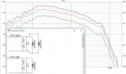
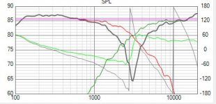
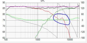
Attached a simulation for the existing 2-driver in parallel (red curve), and the single driver case (green). Both have the same acoustic output (the red obviously is +6 dB in level). The single driver crossover values are on the schematic. Ignore the black curve, it is a sum of both.
Edit: on a single-driver schematic , the shunt R should be doubled (i.e. 40R, not 20R as I showed in a hurry.. very close though)
Edit: on a single-driver schematic , the shunt R should be doubled (i.e. 40R, not 20R as I showed in a hurry.. very close though)
Attachments
Last edited:
Attached a simulation for the existing 2-driver in parallel (red curve), and the single driver case (green). Both have the same acoustic output (the red obviously is +6 dB in level). The single driver crossover values are on the schematic. Ignore the black curve, it is a sum of both.
Edit: on a single-driver schematic , the shunt R should be doubled (i.e. 40R, not 20R as I showed in a hurry.. very close though)
Draki- You are Awesome! A few more questions, the 20R in series with the 5.1 mF Cap(Zobel) should be 40R, right? I have a 1.5mH coil already- would that be close enough to use instead of the 1.6? Do you think I could get by without using the Zobel altogether and just use the coil and cap on the woofer?
Thanks so much.
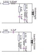
Xman: here is my take on a xover for those two drivers, a little more complex than what you probably hoped. YMMV. Note that a simulation is not a substitute for an exact set of measurements. Take this as a guideline of what can be expected. Other variants are possible.
The LP has modified "zobel" with 5R6 instead the original 40R, plus LCR notch for the 5.8KHz peak (shown with and without).
The HP has a mandatory (for this tweeter, IMO anyway) impedance compensation after the xover.
Xover acoustical @ 3Khz LR12.
The LP has modified "zobel" with 5R6 instead the original 40R, plus LCR notch for the 5.8KHz peak (shown with and without).
The HP has a mandatory (for this tweeter, IMO anyway) impedance compensation after the xover.
Xover acoustical @ 3Khz LR12.
Attachments
Last edited:
Xman: here is my take on a xover for those two drivers, a little more complex than what you probably hoped. YMMV. Note that a simulation is not a substitute for an exact set of measurements. Take this as a guideline of what can be expected. Other variants are possible.
The LP has modified "zobel" with 5R6 instead the original 40R, plus LCR notch for the 5.8KHz peak (shown with and without).
The HP has a mandatory (for this tweeter, IMO anyway) impedance compensation after the xover.
Xover acoustical @ 3Khz LR12.
Thank you for all the help. It's time to get to work on these now
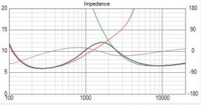
DThe 0.51 Ω resistor is not there, i.e. represents the DC Resistance value ( Rdc) of the voice...er..of the coil .
Correct. Both 0R51 and 0R3 are the inherent R values of the coils (+/- some reasonable tolerance); whereas the LCR' resistor values are the difference between the nominal schematic value and the value of the resistance of the coils (cheaper, high-ish R coils can be used).
- Status
- This old topic is closed. If you want to reopen this topic, contact a moderator using the "Report Post" button.
- Home
- Loudspeakers
- Multi-Way
- Need help with passive crossover for Sanspeak 15W/8434G00 Discovery MidWoofer