Hello!
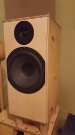
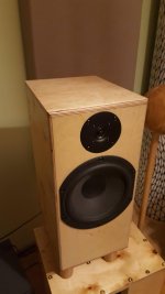
I've been building a speaker out of Peerless 830869 woofer and SB26ADC-04 tweeter. They are in a sealed thin-wall style cabinet made out of varying thickness of BB plywood. For example, the side walls are laminated out of 4mm BB ply, 3mm MDF-style board and with 18mm of bitumen damping (a bit overboard maybe). The enclosure is 230mm wide and 490mm tall. Driver CTC is 170mm. They are finished with beeswax atm, but not very happy about the finish. Probably will lacquer them with high-gloss.
But onto the point. I am seeking advice in crossover design of this speaker. I measured the drivers separately at 25cm and 60cm distances with 0, 20 and 45 degree angles. All of the measurements + impedance files provided by manufacturer are in the .zip file. The naming goes that for example 25@0w is mic 25cm from woofer at 0 degrees. The distance from floor is 100mm if one wishes to gate the measurements (5,6ms gating). Measurement height is between the drivers. I also attached one of my versions of the crossover.
Attachments
Last edited:
Unsure yet, but I have a long weekend ahead of me, a big stash of components and some wire clips ")
That's why I started the thread, maybe we can figure out a nice crossover with even freq. response and good phase matching. Everyone has got their preference on the topology. I'll try the best looking ones posted here (if I have the components) and measure the results.
That's why I started the thread, maybe we can figure out a nice crossover with even freq. response and good phase matching. Everyone has got their preference on the topology. I'll try the best looking ones posted here (if I have the components) and measure the results.
I also simulated 3rd order Butterworth which also gave good results. The Peerless is a very smooth woofer with easy breakup, it might be even usable with a Bessel. I have a hard time integrating the phase with lower orders however. I am aiming for crossover point around 1,5k.
Mayuri,
If these are stand-mounts, you aren't taking into account the baffle step well enough. You'll end up with no bass at all. Notice the steep roll-off below 200 Hz to about 40-50 Hz.
Before you get to comfortable with the crossover you need to take that into account.
Also, did you measure appropriate acoustic offset?
Best,
E
Acoustic offset between drivers is about 40mm (determined with moving drivers until you get phase dip at crossover freq). This hasn't been taken into account because simulations show I actually get better phase tracking without matching the offsets. I actually forgot to add the offset in the simulation I did with VituixCAD yesterday, need to re-do them today...
These will be used with subwoofers, so bass is of no importance. What I'm after is natural sounding vocals and instruments.
These will be used with subwoofers, so bass is of no importance. What I'm after is natural sounding vocals and instruments.
Hey Mayuri,
You must use the effective acoustic offsets int he crossover to get accurate phase data. Otherwise your crossover design will not be accurate. This is why many 2-way systems are assymetrical and / or invert the tweeter.
Even with a subwoofer, the design needs some baffle step compensation to get you flat down to the normal crossover frequencies of 80-100 Hz properly.
IF you are going to use them with room correction however, then no problem. Let the EQ boost the 80-200 Hz range, and design for maximum efficiency. This is actually quite a smart thing to do for home theater use speakers.
Best,
E
Last edited:
For an 8" woofer and 1" dome tweeter, LR4/LR4 will assure safe operation and attenuation of cone breakup effects. The rapid crossover also keeps the phase change from the flat baffle physical offset over a short frequency range.
For an 8" woofer and 1" dome tweeter on a flat baffle, BW3 on the tweeter and LR2 on the woofer introduces enough phase difference to mimic the physical offset. With LR2 the modest midrange coil inductance Le=0.63mH on the Peerless 830869 may not generate enough attenuation of the higher frequency midrange cone breakup.
For an 8" woofer and 1" dome tweeter on a flat baffle, BW3 on the tweeter and LR2 on the woofer introduces enough phase difference to mimic the physical offset. With LR2 the modest midrange coil inductance Le=0.63mH on the Peerless 830869 may not generate enough attenuation of the higher frequency midrange cone breakup.
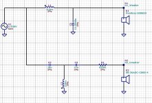
Yes, the acoustic offset is now included. Sorry for the mistake, simply forgot about it yesterday Here is simple Bessel on woofer, BW3 on tweeter. Seems to work well, I will try it later and post results.
As a bonus it uses parts I already have, so no need to buy new crossover parts.
Here is simple Bessel on woofer, BW3 on tweeter. Seems to work well, I will try it later and post results.As a bonus it uses parts I already have, so no need to buy new crossover parts.
Attachments
Last edited:
Hi Mayuri,
With these data of the cabinet dimensions and your measurements, I can make a complete model of your speaker in the Leap simulator. For the driver modelling I will start with the specification data of the drivers and then compare the results with your measurements. Once I have a good fit on your SPL and impedance measurements I can make some crossovers in Leap from my side also and look to all the speaker responses.
And also have a look at the current design of course.
I keep you informed...if you are interested in?
Paul
To measure the acoustical offset, you can measure each driver on its own axis with the microphone at exactly the same distance from the front baffle.
You will see the woofer impulse will start later than the one of the tweeter. Out of this delay time, you can calculate the acoustical offset between the drivers.
To measure the individual SPL responses, it is also better (IMO) to measure each driver on its own axis at the same distance of the front baffle. It is more relevant for the listening position at 3m w.r.t. the radiation angle. If possible also measurements at 1m. At 60cm the baffle step response already starts changing a little w.r.t. the more far field responses, it is on the limit.
What is the depth of the cabinet and what is the distance of the tweeter center from the top of the cabinet? Just for making a correct model for the simulation.
Hello Paul!
Thank you for the offer, and I would be intrigued on what you can do with Leap. I measured the acoustic offset of drivers by playing same 1500Hz tone with both with tweeter out of phase and searching for the deepest null, which happened 40mm behind the woofer flange (coincidentally it is the point where woofer voice coil meets the cone).
I will do the measurements you ask tomorrow. The cabinet is 230mm wide, 494mm high, 300mm deep. The tweeter is 6,5cm from the top of the cabinet and on center line. Woofer is 23cm from top. The internal volume is about 25l sealed. Currenly the box is empty but planning on stuffing with fiberglass OR porting.
Hello Mayuri,
Thanks for the extra info.
If possible also measure the driver impedances. Especially the one of the woofer in the enclosure is interesting to have, to know the value and frequency of the impedance peak. That peak value has its impact on the low frequency X-over response. If you apply cabinet filling (recommended for closed box), the impedance has to be measured with the filling. For the tweeter, it is a check w.r.t. the specification value.
The mechanical offset of 40mm that you get with your measurement at 1500Hz is not the real acoustical offset between the drivers. 40mm is the distance to bring the drivers in phase (or antiphase) at 1500Hz. The acoustical offset can easily be measured in the time domain with the time offset between the impulse starting times. Each driver measured at its own axis at exactly the same distance from the front baffle.
Paul
Hello Paul,
Thanks for the info! Sadly is it not possible to measure impedances for me. I use UMIK-1 and lack a dedicated soundcard for measurements. However, I simulated the box impedance with VituixCAD, it should give an approximation how the sealed box behaves. I took a new set of measurements at respective driver axis, 30cm away and 1m away. I use REW for the measurements. With 1m it has a plenty of room artifacts as my listening room is in fact very small. From the measurements I gathered that the difference between the step response peaks of tweeter and woofer is 66us, which would equal a 2,2cm difference between the acoustic centers. If it is so little, it would be trivial to bring them very closely together by applying a 21mm piece of plywood on top of the current baffle for the woofer area.
Here is the .mdat file with the 4 measurements:
Dropbox - 30cmand1m.mdat
Thank you for the help.
Attachments
Last edited:
Hi Mayuri
22mm acoustical offset is more realistic.
Adding an extra baffle for the woofer is an option, but it will probably change the tweeter SPL a litlle, because of the extra baffle edges close to the tweeter. You have to measure then. Maybe it can be solved in the filter also.
I had a look at your REW measurements at 1m. To eliminate the room reflections I have chosen the IR window only 3.5ms.
These are your REW measurements imported in Leap

From my side I have made driver models in Leap using the driver specification.
This is SPL of the woofer model in Leap compared with your REW measurement.
Model in blue and REW measurement in grey.

And the same for the tweeter.
Model in red and REW measurement in grey

To fit, I gave the measurements an SPL offset of 10.75dB.
I had to increase the woofer SPL of the model with 0.5dB.
You can see some differences.
For the woofer, below 700Hz the model is more correct. Your woofer shows a break up at a higher frequency than the specification shows.
For the tweeter there are some differences at 900Hz and 3500Hz. It is not clear now if these are driver SPL or diffraction differences. I think both.
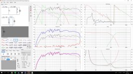
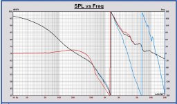
For the curiosity I already simulated your last filter with the Leap models. These are the resuts.
SPL 2.83Vrms 1m

Phase

Impedance

IMO the filter has to be adapted for more low frequency extension. Now the sensitivity is 87dB at 1m. It should be better to make it about 84dB to have more compensation of the baffle step in that way.
Also the SPL flatness and phase alignment maybe can be better.
At first I will improve now the models for a better fit on your measurements.
And after that I will have a closer look to the filter. Do you prefer LR4 at 1500Hz?
Paul
22mm acoustical offset is more realistic.
Adding an extra baffle for the woofer is an option, but it will probably change the tweeter SPL a litlle, because of the extra baffle edges close to the tweeter. You have to measure then. Maybe it can be solved in the filter also.
I had a look at your REW measurements at 1m. To eliminate the room reflections I have chosen the IR window only 3.5ms.
These are your REW measurements imported in Leap
From my side I have made driver models in Leap using the driver specification.
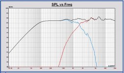
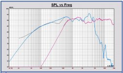
This is SPL of the woofer model in Leap compared with your REW measurement.
Model in blue and REW measurement in grey.
And the same for the tweeter.
Model in red and REW measurement in grey
To fit, I gave the measurements an SPL offset of 10.75dB.
I had to increase the woofer SPL of the model with 0.5dB.
You can see some differences.
For the woofer, below 700Hz the model is more correct. Your woofer shows a break up at a higher frequency than the specification shows.
For the tweeter there are some differences at 900Hz and 3500Hz. It is not clear now if these are driver SPL or diffraction differences. I think both.
For the curiosity I already simulated your last filter with the Leap models. These are the resuts.
SPL 2.83Vrms 1m
Phase
Impedance
IMO the filter has to be adapted for more low frequency extension. Now the sensitivity is 87dB at 1m. It should be better to make it about 84dB to have more compensation of the baffle step in that way.
Also the SPL flatness and phase alignment maybe can be better.
At first I will improve now the models for a better fit on your measurements.
And after that I will have a closer look to the filter. Do you prefer LR4 at 1500Hz?
Paul
I prefer a filter that works 3rd or 4th order is a must for the tweeter, but I think the woofer can work with a lower order, maybe even Bessel.
When you attach files for your message, if you don't use the [ ATTACH ] tag, they will show a list like in my messages.
Out of curiosity, can you also simulate with the tweeter coil being 0,22mH?
3rd or 4th order is a must for the tweeter, but I think the woofer can work with a lower order, maybe even Bessel.When you attach files for your message, if you don't use the [ ATTACH ] tag, they will show a list like in my messages.
Out of curiosity, can you also simulate with the tweeter coil being 0,22mH?
Mayuri,
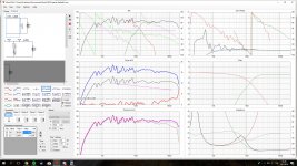
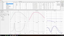
I have done a data splice in Leap in a way that the REW measurements are used for the model above 700Hz. Now the SPL of the drivers are correct from low to high frequecies. These curves can be used for further filter design.
In the plot you can see the SPL of the models in color and your REW measurements in grey (almost hidden now ).
Do you have a calibrated microphone for your measurements?
I have done a data splice in Leap in a way that the REW measurements are used for the model above 700Hz. Now the SPL of the drivers are correct from low to high frequecies. These curves can be used for further filter design.
In the plot you can see the SPL of the models in color and your REW measurements in grey (almost hidden now
).Do you have a calibrated microphone for your measurements?
Attachments
- Status
- This old topic is closed. If you want to reopen this topic, contact a moderator using the "Report Post" button.
- Home
- Loudspeakers
- Multi-Way
- Peerless 830869 + SB26ADC-04 crossover help?