Paul, it is fine to change the cap values. From your simulation I see we can get better FR with 15uF and 33uF than with 18uF and 33uF. I'm interested in getting the best response out of these, this is why the stepped baffle to physically time-align is also an option.
Last edited:
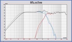
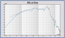
Results from aforementioned filter. 1m measurements are gated 3,5ms, 30cm measurements are only smoothed 1/24 oct. Looks pretty decent.
Dropbox - filter1.mdat
Dropbox - filter1.mdat
Attachments
Mayuri,
For your last simulation I have different results in Leap than yours.
Also your filter electrical transfer response is different for the woofer.
In Leap it looks not so good. The woofer has a strong peak at 1200Hz.
I will check also. It looks that your woofer impedance is different from mine.
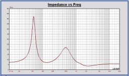
I have attached my woofer impedance in the cabinet.
For your last simulation I have different results in Leap than yours.
Also your filter electrical transfer response is different for the woofer.
In Leap it looks not so good. The woofer has a strong peak at 1200Hz.
I will check also. It looks that your woofer impedance is different from mine.
I have attached my woofer impedance in the cabinet.
Attachments
Results from aforementioned filter. 1m measurements are gated 3,5ms, 30cm measurements are only smoothed 1/24 oct. Looks pretty decent.
Dropbox - filter1.mdat
The measurement looks conform the Leap simulation, but you measure a little higher level for the tweeter. Also the tweeter shape is a little different around 2kHz. It should fit better.
Maybe one time also measure again the driver responses without filter.
Then I can compare a second time with the models.
Mayuri, your zma files do not contain any valid phase data, that's why your simulations are not correct. Attached are files that should work better.")
Hi Dissi,
yes, that explains the difference between the simulations
Here are measurements with and without filters at 30cm and 1m distances. Filter is the one in the attachment.
Dropbox - filter2.mdat
Dropbox - filter2.mdat
Thanks for the tip! However, when I try to load the files you provided into VituixCAD, it gives an error and says they don't contain frequency data.Mayuri, your zma files do not contain any valid phase data, that's why your simulations are not correct. Attached are files that should work better.
Attachments
Mayuri,
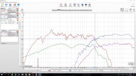
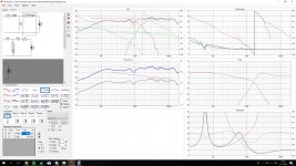
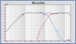
I have checked the Leap driver models versus the REW measurement filter 2. There is a good fit.
You can see in attach, models in color, measurements in grey.
I have checked the Leap driver models versus the REW measurement filter 2. There is a good fit.
You can see in attach, models in color, measurements in grey.
Attachments
Mayuri,
I have checked the Leap driver models versus the REW measurement filter 2. There is a good fit.
You can see in attach, models in color, measurements in grey.
Alright, so the simulations are correct. I'm going to make some more tests tomorrow when I get my soldering iron back (borrowed it to a friend for the a weekend, a mistake in hindsight). I'll check my own filter first and if it is unsatisfactory I'll order the parts for this filter:
Also I got the speakers with terminal cups atm, will detach them and use the hole for a test port as well (4cm diameter with 10cm lenght for 33Hz tuning). It should push the F3 a little lower.
Mayuri
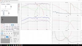
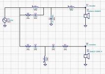
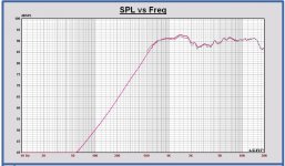
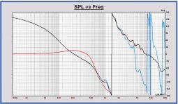
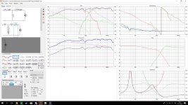
Here the simulation with 15 uF and 33 uF. Coils are 3.9 mH / 0.30 Ohm and 0.22 mH / 0.82 Ohm. Z is minimum 3.25 Ohm. Serial resistor in tweeter filter 2.7 Ohm now.
This is the best I can make with this filter configuration.
Paul
Here the simulation with 15 uF and 33 uF. Coils are 3.9 mH / 0.30 Ohm and 0.22 mH / 0.82 Ohm. Z is minimum 3.25 Ohm. Serial resistor in tweeter filter 2.7 Ohm now.
This is the best I can make with this filter configuration.
Paul
Attachments
Thank you kindly for your help Paul, Erik and Dissi!
I will post measurements of effects of porting and filters on the following week. I will probably put a small resistor in series before the tweeter filter to push level a bit down and to bring impedance up around 2kHz.
You are very welcome Mayuri. I find it always interesting to have some feedback of practical realizations of something on paper.
Just to make sure: are you simulating this filter I posted earlier in here?Mayuri,
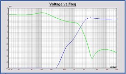
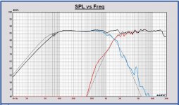
I have made Leap models conform your REW measurement filter 2. They are a little different. See the SPL with filter V7.
Paul
http://www.diyaudio.com/forums/mult...-sb26adc-04-crossover-help-5.html#post5315730
Just to make sure: are you simulating this filter I posted earlier in here?
http://www.diyaudio.com/forums/mult...-sb26adc-04-crossover-help-5.html#post5315730
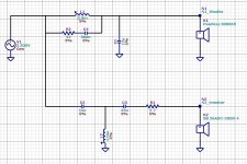
No, it is my last filter version 7, schematic in attach.
Attachments

The minimum impedance is too low, and with many amplifiers may lead to a depressed output in the 2-5kHz range.
I would strongly suggest rethinking it, but it is impossible to do if you insist on keeping the caps.
Best,
E
Erik,
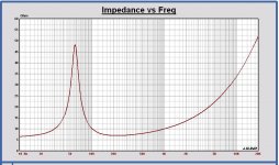
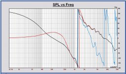
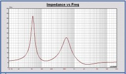
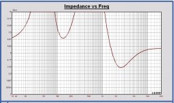
I agree, this is on the limit. With the last filter version 7, the minimum impedance is 3.25 Ohm at 2.5 kHz, impedance plot in attach.
The serial resistance of the 0.27mH coil has to be 0.82 Ohm.
I am looking to improve it. The problem is that this tweeter needs some filter boost between 2 and 5 kHz to become flat.
Paul
Attachments
Last edited:
Surprise measurements! Got my soldering iron back, which means that I immidiately soldered together a filter (attachment) with the parts I got at hand currently. Tried out a port in place of terminal cup in this version, 4cm diameter 11cm long (should be 33Hz tuning). Ordered the parts for the filter v7 Paul made.
Dropbox - filter3.mdat
Dropbox - filter3.mdat
Attachments
Last edited:
- Status
- This old topic is closed. If you want to reopen this topic, contact a moderator using the "Report Post" button.
- Home
- Loudspeakers
- Multi-Way
- Peerless 830869 + SB26ADC-04 crossover help?