Hi!
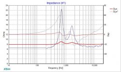
Bought a pair of B&C DE500 comp. drivers. Want to cross them around 1400Hz but looking at the impedance graph I see a hump from 1kHz to 2kHz. It goes from 8 ohms around 900Hz to 20ohms peak around 1,5kHz and drops again.
What values do I need to apply on the zobel to get around 7ohms constant? Is it doable?
Thanks for your help!
Hi Drummer,
I'm sure it it doable, but not sure if "Zobel" is the right filter.") That would help you for the impedance rise above 2kHz.
That would help you for the impedance rise above 2kHz.
I am going to suggest you simulate the entire design first, and then see how big a deal it is. If you use XSim, use the "filter response (dB)" chart to see how that affects you at the end of the day. THEN you can go about working on an impedance compensation network.
Of course, alternatively, you could use something terribly simple like a plain resistor in parallel.
Best,
E
I'm sure it it doable, but not sure if "Zobel" is the right filter.
That would help you for the impedance rise above 2kHz. I am going to suggest you simulate the entire design first, and then see how big a deal it is. If you use XSim, use the "filter response (dB)" chart to see how that affects you at the end of the day. THEN you can go about working on an impedance compensation network.
Of course, alternatively, you could use something terribly simple like a plain resistor in parallel.
Best,
E
What are you using below 1400 hz? Mostly asking if you need to pad the driver.
Also, what sort of slope do you want?
If using at least a second order slope and padding by a few db, I would put about 25 ohms in series with the driver and also make the choke act as a transformer with a tap.
I like to avoid L pads especially with compression drivers.
Also, you might shoot for a lower q filter at 1400 hz an expect a higher q response in the end.
Hi Drummer,
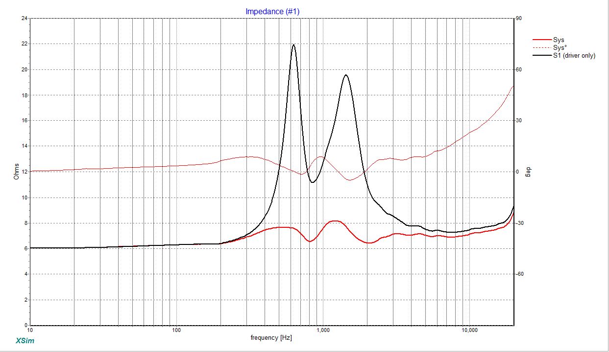
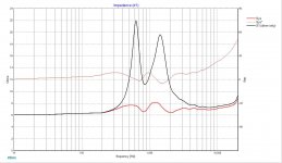
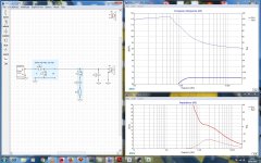
This sounded fun, so I did a little more work. First, I used Virtuix's SPL trace (under Tools) to copy an image of the driver's impedance. I'm not sure if it is exactly your driver, but it seems close. Imported that into XSim, and then used the "Circuit Blocks" menu to add a pair of notch filters. You can see the difference between the original, and filtered here:
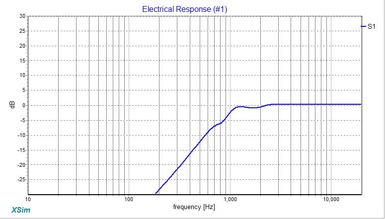
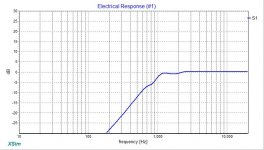
Lastly, I added a 1kHz, 2nd order high pass filter so I could examine the filter's electrical response, which is now pretty close to ideal:
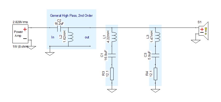
The final schematic is below:
This sounded fun, so I did a little more work. First, I used Virtuix's SPL trace (under Tools) to copy an image of the driver's impedance. I'm not sure if it is exactly your driver, but it seems close. Imported that into XSim, and then used the "Circuit Blocks" menu to add a pair of notch filters. You can see the difference between the original, and filtered here:
Lastly, I added a 1kHz, 2nd order high pass filter so I could examine the filter's electrical response, which is now pretty close to ideal:
The final schematic is below:
Attachments
BTW, this is also a very good example of why simulation is a good idea. Depending on exactly where your HP filter is, and the Q, one or both of these impedance notch filters may become unnecessary, saving you some dough! Further, if we had been tempted to add an actual Zobel for the impedance rice at the top octave, the simulation shows that with this choice of HP filter there's really no need at all.
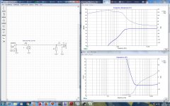
I almost forgot, here is a picture of the Electrical response without the notch filters:
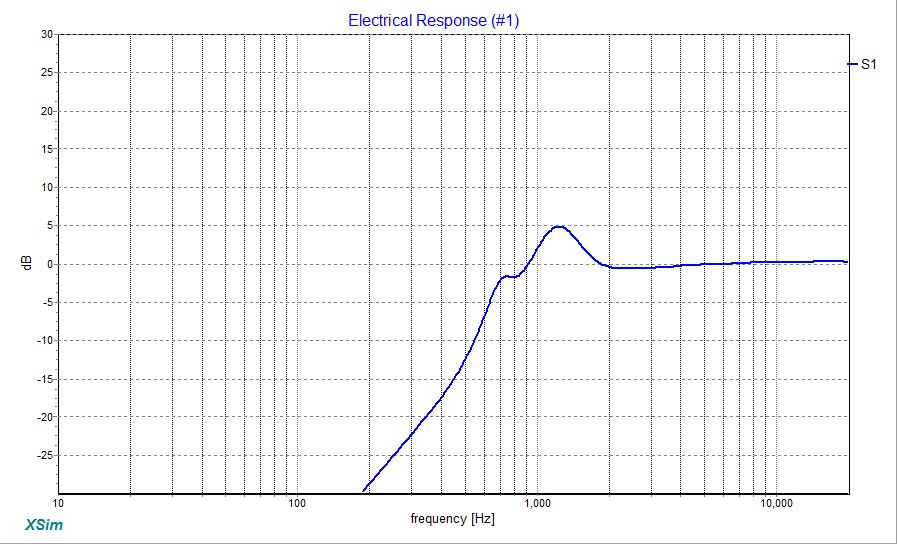
While it does look bad, your choice in HP filter could eliminate one or both of those notch filters. I am pretty sure the first one with the 4mH coil is pretty optional. Save yourself some dough!
Best,
E
I almost forgot, here is a picture of the Electrical response without the notch filters:
While it does look bad, your choice in HP filter could eliminate one or both of those notch filters. I am pretty sure the first one with the 4mH coil is pretty optional. Save yourself some dough!
Best,
E
Attachments

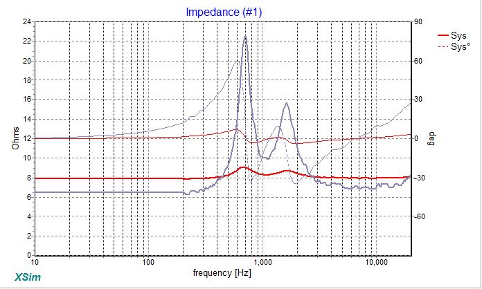
Meh, I did even better. I'll just upload the whole thing so you can play with it.
The magnitude of impedance in the humps is now less than 1 Ohm, but again, your wallet uber alles! Make sure the notch filters actually matter to you at the end of the day.
I'll just upload the whole thing so you can play with it. The magnitude of impedance in the humps is now less than 1 Ohm, but again, your wallet uber alles!
Make sure the notch filters actually matter to you at the end of the day.Attachments
Usually the resistive padding ( necessary to match a compression driver to a direct radiating woofer ) smooths the impedance spikes into very benign bumps ( therefore; additional impedance compensations designed to flatten them out, become un-necessary ).
Seen above is the effect of an Altec style, 10db "T-Pad" .
Seen above is the effect of an Altec style, 10db "T-Pad" .
Attachments
Last edited:
Usually the resistive padding ( necessary to match a compression driver to a direct radiating woofer ) smooths the impedance spikes into very benign bumps ( therefore; additional impedance compensations designed to flatten them out, become un-necessary ).
That's exactly what I just wanted to say. The compression driver will very likely be too loud anyway, so a voltage divider is needed. On many horns a bypass-capacitor is also needed to boost the upper end, that's a lot cheaper than a zobel filter for the rising impedance (which is very tame for the DE500) and costs less power too.
Erik thanks a lot!
Now I see how to approach to this.
I used box design software, but not for filters.
You're right it would work taming only the second impedance hump. (And I dont have 4mH coils for the first filter)
I need also some attenuation since I'll use a pair of beymas 8p300 running in parallel for mid/bass. Around 10db attenuation needed.
Daqvin, id prefer not using l pads but never used a transformer this way. Could you explain a bit more how to calculate the values?
And what about putting a parallel resistor to smooth that humps and use a first order filter at around 10-15k. I've read this can be used to pad down highs.
Anyway, when I get home, I'll play with the filter simulation.
Erik, thanks again for taking your time with this.
Regards.
Drummer, I don't know enough atout T-Pads, but I do remember what EarlK is talking about, that is worth researching before my notch filters, certainly cheaper! You should examine the filter function for any idea before implementing.
Make sure you evaluate the wattage at each resistor too. XSim has a chart for that.
Best,
E
Make sure you evaluate the wattage at each resistor too. XSim has a chart for that.
Best,
E
Erik,
Been playing with the simulation you sent me. Man, this is addictive!
As you suggested, removed the first notch filter, and increased the cutoff freq for the hpf to 1,7kHz.
Added a bypass capacitor to pad down the driver and it seems pretty good. What do you think?
Now I have to figure out how to add the FRDs/ZMAs for the woofers.
Thanks again for your help.
Remember what you were told by others, it may not be needed to design these networks at all. First start with a high pass and padding resistors, then observe if there is anything wrong with FR in the impedance peaks regions and if there really is, then consider to include some.
A - Lojzek is 100% correct.
B - If we are just playing, the cap is a bad idea for two reasons:
1 - If you notice the transfer function wtihout it, the response is flat, so no reason to flatten the impedance.
2 - Notice the minimum impedance has now dropped to nearly 2 Ohms! If you were trying to get a flat impedance, you have gone too far the opposite direction.
Remove your high pass filter, and examine the impedance again and the problem will become more obvious. This is why Zobel's have a resistor in series.
Best,
E
Put another way, the main purpose of any impedance compensating network is not a flat impedance, but well-behaved electrical transfer function once the filters are in place. They help the high pass or low-pass filters work ideally.
If you didn't have high pass/low pass filters and worked exclusively with solid state amps, then this work is unnecessary. Indeed, active speakers don't bother with this at all.
The secondary purpose, and it is a big cheat, is to nudge driver phase a little bit.
Best,
E
If you didn't have high pass/low pass filters and worked exclusively with solid state amps, then this work is unnecessary. Indeed, active speakers don't bother with this at all.
The secondary purpose, and it is a big cheat, is to nudge driver phase a little bit.
Best,
E
Last edited:
Erik, you´re right, there is not a flat impedance curve with the bypass cap, but I thought it could work since the freq response graph showed it flat with no peaks.
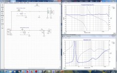
Anyway tried what Icg, Earl and Lojzek said. An L pad made the humps disappear.
The problem is that I dont know yet how much padding I´ll need and playing with the resistors values changes the whole circuit.
This xover is simpler and can use smaller coils for the same crossover freq but wont the resistors affect sound? I have read somewhere that padding resistors made some drivers to sound dull.
This is the schematic I got now.
Thanks again!
Attachments
Last edited:
I think there's something about over damped woofers, with low Qms or something like that. Forgot.
Yep. Please keep in mind this is all purely electrical until you add the driver's actual FR!
One thing to notice is the rise in output at the top octave. This is caused by the rising inductance in the coil. Well, take a look at the driver. The natural top octave is supressed, so you actually WANT the impedance to rise, and get a boost there. It won't fully make up for it, but this is a case where the Zobel is actually counter productive.
Best,
E
eriksquires is probably the only person who loves Xsim even more than I do.
Mr. Waslo is an audio god in my most unhumble opinion. So my bias is made clear.
I have learned the hard way: you may find an optimal sounding crossover by just doing it by ear or simple level measurements but what you will learn by using XSim will show you, as it did for me, what you think will work, what everyone tells you to use, will not be optimal.
If you want to get it right and learn lots of very interesting things along the way, get REW, or something like it, that allows to you take impedance measurements. I would recommend mounted in the horn along with any other drivers you will use in the network.
Measure the frequency response of each driver, both near-field and at your listening position. I have found I got better insights into what to do with listening chair measurements. The predictions were closer since the full system measurement is taken from the listening chair.
Load these files into Xsim and have some real audio kook fun playing around with configurations. Running through values so you can see the trends in that position. But then I still enjoy playing FREECELL so I may be easily hypnotized by crude video games. But you learn something from XSim. You will develop a conception of what is really going on in your crossover. It will be a collaboration. Xsim is a great audio friend to have around.
I found getting the system flat, and this may be characteristic of compression drivers, that it would not sound right at all. I am using John Inlow's very large mouth horns for the 2441. It must concentrate the intensity, at the listening position, which seems to be ignored by the microphone. I am using the "calibrated" (USB stick), I think it is the DAYTON, sold by people who offer this service at a reasonable price.
When I stand in the room while a measurement is being made, even with a downward slope from 3 kHz, it sounds even in level to my ears. I know I am not the first person to notice this! You can make it measure (I am speaking only of compression drivers, since that is all I know) "flat" but you will not like it unless you have an overly damped room.
There is no question the parallel resistor is the great leveler. I have read folks who say this will decrease the dynamics. If there is a reduction it is minimal. One thing for sure you can hear this quite clearly! It is close to magic.
If you think you are going to, with one try, come across the best values for your network you are going to be disappointed. You will find that what you end up with is quite different from what you started with. And you will be glad you stuck with it.
As Herb Reichert said in an article in SOUND PRACTICES; he was told to "remember the loudspeaker plays the room" so you have to tailor your loudspeaker/crossover to the room and improve your room to get great sound. The advantage the DIYer has is that one can get sound that cannot be brought home in boxes.
Hi Rick.
I know it wont be the optimal filter and dont know how accurate are those simulations, but I want to make a filter to start with, and then modify or "fine tune" it.
I'll take a look to REW too, never used it.
Anyway Im beginning to think that it could be a too ambitious project since I never built an speaker with parallel woofers and with a diy horn+comp driver.
Id like to make it work, but have tons of questions.
The more I read, the more questions I have.
Nos im not sure if this is a good xover freq to start with ir if I should start líder (around 1kHz). What tune freq for the horn?
Thanks for your patience...
Hi again!
I have some updates:
Captured the manufacturers impedance and freq response curves using VituixCAD. So finally got the needed .zma and .frd files for my drivers. (Thanks Erik!)
After some hours I got the attached schematic. I have almost all components for those values.
Please, let me know if it seems like a reasonable xover circuit for those drivers.
Thanks!
Attachments
- Status
- This old topic is closed. If you want to reopen this topic, contact a moderator using the "Report Post" button.
- Home
- Loudspeakers
- Multi-Way
- comp driver zobel help!