Hi,
Surfing around on the web the formula
f3 = 115 / (baffle width in metres)
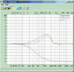
often appears. When I run my own program The Edge it appears as if this yields a much too high frequency. In the image below, a typical floorstander is simulated with a baffle width of 0.2 m, which should give an f3 of 575 Hz. Assuming full compensation, the two frequencies to enter in The Edge would be 406 and 812 Hz. This is the green curve. If I let The Edge calculate the values, I end up with 151 and 302 Hz. This is the red curve, and this compensation is shown in blue.
What I really am interested in is hearing from you all about practical experiences with the equation above, does it compensate the baffle step well, or do you still see effects like the green curve after applying it?
Surfing around on the web the formula
f3 = 115 / (baffle width in metres)
often appears. When I run my own program The Edge it appears as if this yields a much too high frequency. In the image below, a typical floorstander is simulated with a baffle width of 0.2 m, which should give an f3 of 575 Hz. Assuming full compensation, the two frequencies to enter in The Edge would be 406 and 812 Hz. This is the green curve. If I let The Edge calculate the values, I end up with 151 and 302 Hz. This is the red curve, and this compensation is shown in blue.
What I really am interested in is hearing from you all about practical experiences with the equation above, does it compensate the baffle step well, or do you still see effects like the green curve after applying it?
An externally hosted image should be here but it was not working when we last tested it.
This simulation is identical to yours except the baffle is square. You can see that the "rule of thumb" is very close to the Edge's suggested result.
Obviously the 115/w does not take baffle height into account at all. I would *think* that your method would be more accurate...I wish I could supply the needed empirical data.
Unfortunately not many people have the equipment to be able to measure 1-2dB ripples in the response.
Obviously the 115/w does not take baffle height into account at all. I would *think* that your method would be more accurate...I wish I could supply the needed empirical data.
Unfortunately not many people have the equipment to be able to measure 1-2dB ripples in the response.
Attachments
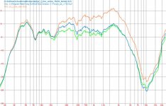
Well, I have made some measurements, but not with the exact value The Edge suggests. The baffle size is 220x1000mm and I have used two coils for the test :
The first value was 1,5mH which is close to Olson's formula : L=Wb*R/1.021 which gives ~1,8mH.
The second value is 2,7mH which is far from the 4.2mH The Edge calculates with 150Hz(f1) and 300Hz(f2), but showing the direction where the compensation goes. This is like I have used 230/460Hz for the compensation points.
I start to believe that your calculations are correct , however with the bigger value the sound is thinner (?), instruments and human voice lacks some body.
First here is the measurement.
Orange line=raw driver in box, Blue=1,5mH||8ohm, Green=2,7mH||8ohm
Attachments
This is exactly the kind of data I was looking for. It is hard to say which one of the green and blue that would be the best, but it definitely appears as if 4.2 mH would be too much. To the defence of The Edge one could say that the resistance of the loudspeaker probably isn't 8 ohms, but rather 6 ohms, and this would give an L of 3,1 mH which still appears a bit high.
Thanks!
Thanks!
Well, the hump is not *that* big, only + 2-4 dB, and with a bit of good will, it can *maybe* be seen there. But I agree that it is far from crystal clear, there seems to be a lot more going on in this speaker.
Might I ask, how was this measurement performed? It does not look lika a MLS measurement.
Might I ask, how was this measurement performed? It does not look lika a MLS measurement.
Yes, it's an MLS measurement from around 1 meter and I had to apply a 1/2 octave smooting to it to be hmmm.. more readable.
Well, you are right, there is a small hump at 6-700Hz, but there is a bigger one one octave bellow which annoys me a bit, because it seems hard to get rid of it.
Also, if I would do the same test from 2 meters I would get a different result. My feeling is that BSC probably requires a more complex compensating network.
Yes, BSC in its simplest form assumes a spherical cabinet. From what I have seen in The Edge it appears as if most flat baffle shapes have a reasonably large hump added to this at about the upper of the two step frequencies. This could probably be compensated for with a better network. However, given the dimensions you have on your baffle, I don't think that the hump at 200-400 Hz is caused by the BS.
Could you provide more detail on what driver you use. That is, if you want me to say anything about it. Could it be that the hump is actually two dips at 170 and 500 Hz? That would fit with the 1st and 3rd resonance along the 1000 mm of the box. I don't know why the second mode would not be excited, but that could be due to the driver placement. Do you have stuffing inside the box?
Could you provide more detail on what driver you use. That is, if you want me to say anything about it. Could it be that the hump is actually two dips at 170 and 500 Hz? That would fit with the 1st and 3rd resonance along the 1000 mm of the box. I don't know why the second mode would not be excited, but that could be due to the driver placement. Do you have stuffing inside the box?
This is actually a Proac clone and I experimenting with the baffle step, because I think that a single 1,5 or 1,8mH inductor doesn't coop well with the issue.
The woofer center is located around 750mm from the floor and the box is dampened.
You are right about the 300Hz hump. I have looked at the measurements I have made and it's "moving" between 200-400Hz depending on the measuring distance, so it's probably a room reflection, but only a single hump.
Zozo
Hmm, interesting. Placing the driver at 750 mm would not excite the second mode! A funny experiment would be to put the microphone inside the box and see if you have resonances at 170 and 500 Hz. If it is a BR (I am not familiar with the Proac) the mic can easily be inserted through the vent. Put the mic at the floor inside the box top see all resonances. If you have resonances, it might be that you need more stuffing.
As you say, the fact that the hump is moving talks against this theory, but in the hunt of the cause, another measurement could IMO do no harm...
As you say, the fact that the hump is moving talks against this theory, but in the hunt of the cause, another measurement could IMO do no harm...
- Status
- This old topic is closed. If you want to reopen this topic, contact a moderator using the "Report Post" button.
- Home
- Loudspeakers
- Multi-Way
- BSC, how well does 115/W perform