What makes you doubt your phase and time alignment based on those two IR plots? Your waterfall plot, the sum and dip at the listening spot as presented way earlier all confirm your alignment at the measured spot of ~0.9 m.
Hi wesayso, I think the doubt comes from how the posted impulse and step response plots look. They could use some tightening up, at least IMHO.
I've found in time and phase aligning a bunch 3 and 4 way setups, that sometimes I hit the puzzler where freq response looks nice, where there is clearly good summation thru crossover, and heck even phase looks good.....but still, the impulse plot looks a little wonky, like in Michael's case.
It usually means, that time and phase have been traded one for the other inappropriately. I mean, take this case where x-over is at about 2700 Hz, which has a period of 1000ms/2700=0.37ms. If time alignment is off by 1/2 that period, or 0.18ms, you will most likely invert the polarity, to make you think you got everything right. Whereas really you didn't and it will show up in the impulse and step response ( and also in less that optimal summation away from x-over center freq.)
Not trying to diss REW, but I find it very difficult to use for working out time and phase alignment correctly. REW certainly excels at dialing a speaker into a room..hey, maybe that's why it's called Roomeqwizard Lol.
But the estimated IR shift makes aligning multi-ways very difficult IMO. And waterfalls, etc, seem really more about the room than the speaker itself...or at least compared to simple magnitude, phase, and impulse plots.
I'm spending some time with REW now and hope to be able to offer some suggestions for making time and phase alignment easier using Timing Ref and Loopback...where it gets closer to the ease of dual FFT. All FWIW, and best! mark
Hi Mark,
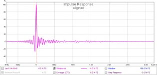
As we are not talking about a FIR corrected crossover here and are past the first order crossover we should expect phase turn, which will show up in the IR.
What bothers me more are the peaks after the -down-up- main peak, seen in the tweeter + filter IR. It's still there in the complete system IR. This is something I would want to solve (acoustically).
With REW you can find the time alignment, it's not like the IR and FR plots are the only tools available") . I think the newer option to use a signal for alignment could be a neat trick. I have not looked it up yet.
. I think the newer option to use a signal for alignment could be a neat trick. I have not looked it up yet.
Loopback has been the way to get real timing information. As we could not rely on the timing to be exact between sweeps. Loopback solved that. Maybe the new feature works, but I wouldn't know how it works yet. I though a sweep would be preceded by a chirp, line up those chirps and the rest of the following sweep measurement is aligned.
One can always use the filtered IR to look at or close to the frequency where the crossover is. Just filter both woofer and tweeter information with 1/3 oct at 2500 Hz and in overlay view the wavy shapes of woofer and tweeter should line up if we have enough overlap at the crossover.
A short waterfall plot, like I asked for can be revealing for crossovers. A longer one would not show that much about the crossover itself.
We haven't even looked at the wavelets yet, another way to look into the timing. Especially with the new features added there in the latest release of REW. This could also show proper timing, much like APL_TDA.
That would be the next question from me. It would present a time map viewed from above.
If this were my project, I would not rest until I knew what caused the blips after the main peak. That's the most eye catching for me. I think if we solve that, the dip at 10 KHz would probably be gone too.
As we are not talking about a FIR corrected crossover here and are past the first order crossover we should expect phase turn, which will show up in the IR.
What bothers me more are the peaks after the -down-up- main peak, seen in the tweeter + filter IR. It's still there in the complete system IR. This is something I would want to solve (acoustically).
With REW you can find the time alignment, it's not like the IR and FR plots are the only tools available
. I think the newer option to use a signal for alignment could be a neat trick. I have not looked it up yet. Loopback has been the way to get real timing information. As we could not rely on the timing to be exact between sweeps. Loopback solved that. Maybe the new feature works, but I wouldn't know how it works yet. I though a sweep would be preceded by a chirp, line up those chirps and the rest of the following sweep measurement is aligned.
One can always use the filtered IR to look at or close to the frequency where the crossover is. Just filter both woofer and tweeter information with 1/3 oct at 2500 Hz and in overlay view the wavy shapes of woofer and tweeter should line up if we have enough overlap at the crossover.
A short waterfall plot, like I asked for can be revealing for crossovers. A longer one would not show that much about the crossover itself.
We haven't even looked at the wavelets yet, another way to look into the timing. Especially with the new features added there in the latest release of REW. This could also show proper timing, much like APL_TDA.
That would be the next question from me
. It would present a time map viewed from above.If this were my project, I would not rest until I knew what caused the blips after the main peak. That's the most eye catching for me. I think if we solve that, the dip at 10 KHz would probably be gone too.
What bothers me more are the peaks after the -down-up- main peak, seen in the tweeter + filter IR. It's still there in the complete system IR. This is something I would want to solve (acoustically).
Hi wesayso, Yep, bothers me too.
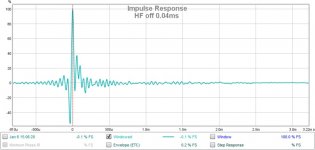
I really have to believe it's timing. Below are a couple of impulses from the same speaker setup. First is pretty well time aligned. Second has a deliberate mis-alignment of only 0.04ms.
Notice the undershoot before the main peak, and the second smaller peak past the main.
Michael, if you read this, it has me rethinking advising you so swap polarity along with a 1/2 cycle time alignment adjustment. You may just be out a wee bit.... as in this example....only measuring will tell
Oh, worth mentioning...the misalignment is on a HF unit crossing at 6300Hz...so not apples to apple by any means...but does show how sensitive impulse can be. Sorry I don't have any speakers that cross over more around 2800Hz.
Attachments
Last edited:

But the standard reference for the audibility threshold of time-screw-up is Blauert and Laws who report approximately the following thresholds for audibility:
Frequency Threshold of Audibility
8 kHz 2 msec
4 kHz 1.5 msec
2 kHz 1 msec
1 kHz 2 msec
500 Hz 3.2 sec
(quoted from John L. Murphy)
Looks like we are talking two full cycles of error at mid-range (720-degrees or 1000 milliseconds) before it can be detected in a lab setting. But hard to know how that works at low freq because hearing sometimes reckons in time and sometimes in cycles.
Isn't that relevant, factual, and objective information?
B.
Sorry to keep everyone waiting.
All measurements are now done at 85dB instead of 95dB. As I suspected, 95dB was too high, hence the slew rate limit on the earlier step response.
This is the new STEP response at 85dB.

I found a digital delay in my inventory which has the resolution required. The unit is a Rane AD22B. This is with 0.09ms delay for the tweeter. The tweeter has to be wired in Reversed polarity when the delay is applied.

All measurements are now done at 85dB instead of 95dB. As I suspected, 95dB was too high, hence the slew rate limit on the earlier step response.
This is the new STEP response at 85dB.
I found a digital delay in my inventory which has the resolution required. The unit is a Rane AD22B. This is with 0.09ms delay for the tweeter. The tweeter has to be wired in Reversed polarity when the delay is applied.
Dare I ask why you are chasing the STEP response of a design that had first order crossovers?
Hi wesayso
I don't quite understand. My crossover is asymmetric, not first order.
I just wanted to see how the step would change if the tweeter is delayed.
What does the IR, FR and early waterfall look like now?

Impulse Response of Speaker with 0.09ms delay on tweeter (wired in reverse)

FR and Phase. Phase at 2.7K has actually shifted sightly.

CSD at 5ms Rise time

CSD at 100ms Rise time
The early waterfall rise time is too long, letting in the reflections, so we can't see what's happening at the crossover. We do see it does not sum like before (lower SPL at the crossover).
You see the combined phase, which looks cute and flat on first sight, except for that wiggle at 10 kHz. @Mark, you see that phase wiggle? That's part of the cause of the wiggles in the IR from the tweeter. That had nothing to do with the summing of woofer and tweeter.
I don't think this is the ideal handover for this asymmetric crossover. Just my opinion.
I also believe you should choose a design axis between woofer and tweeter too. Look at the JBL papers for inspiration, imagine how your current setup is going to change at larger distances. Do you see what JBL did and why? I showed a simple graph shoing the difference in distance between tweeter and woofer at a larger distance. You have the actual setup, Draw up a simple picture, much like the one from JBL and plan where both the null axis end up (preferably not at the listening spot).
The IR and STEP is just a rendering of the energy hitting the microphone. You can't see everything at once, you can pull it apart to see what's really happening.
The FR alone shows you don't have an ideal summing here.
The old graph without the delay:

See how this one has less of a dip at the crossover? You can see it in the phase curve as well. We could look at a wavelet, zoomed in to verify.
A triangle shape STEP could be expected using first order crossovers. But that doesn't mean it's the right shape for your current asymmetric setup. At least not without any phase manipulation.
What is your goal here? Do you want to check the time alignment at the crossover?
You see the combined phase, which looks cute and flat on first sight, except for that wiggle at 10 kHz. @Mark, you see that phase wiggle? That's part of the cause of the wiggles in the IR from the tweeter. That had nothing to do with the summing of woofer and tweeter.
I don't think this is the ideal handover for this asymmetric crossover. Just my opinion.
I also believe you should choose a design axis between woofer and tweeter too. Look at the JBL papers for inspiration, imagine how your current setup is going to change at larger distances. Do you see what JBL did and why? I showed a simple graph shoing the difference in distance between tweeter and woofer at a larger distance. You have the actual setup, Draw up a simple picture, much like the one from JBL and plan where both the null axis end up (preferably not at the listening spot).
The IR and STEP is just a rendering of the energy hitting the microphone. You can't see everything at once, you can pull it apart to see what's really happening.
The FR alone shows you don't have an ideal summing here.
The old graph without the delay:
See how this one has less of a dip at the crossover? You can see it in the phase curve as well. We could look at a wavelet, zoomed in to verify.
A triangle shape STEP could be expected using first order crossovers. But that doesn't mean it's the right shape for your current asymmetric setup. At least not without any phase manipulation.
What is your goal here? Do you want to check the time alignment at the crossover?
Last edited:
But the standard reference for the audibility threshold of time-screw-up is Blauert and Laws who report approximately the following thresholds for audibility:
Frequency Threshold of Audibility
8 kHz 2 msec
4 kHz 1.5 msec
2 kHz 1 msec
1 kHz 2 msec
500 Hz 3.2 sec
(quoted from John L. Murphy)
Looks like we are talking two full cycles of error at mid-range (720-degrees or 1000 milliseconds) before it can be detected in a lab setting. But hard to know how that works at low freq because hearing sometimes reckons in time and sometimes in cycles.
Isn't that relevant, factual, and objective information?
B.
It escapes me why this would be relevant information to design a crossover between a woofer and a tweeter. If we get it wrong from the start it will never become right again. You may not believe in an IR, but it does hold all the information we need to get it right. We aren't even talking about linear phase etc. Just a passive crossover.
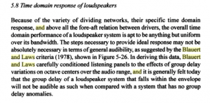
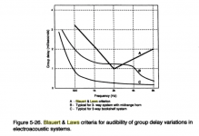
But the relevance does not escape John Eargle. Below are cuts from his foundational textbook (sorry, Google doesn't support text quotes only jpgs of the book).It escapes me why this would be relevant information...
I gather that Blauert and Laws worked carefully, rather like Toole. A panel was trained to be able hear time misalignments and then tested to see their threshold. See my previous post for the data. And even if they are off by, say, 50%, that's way grosser than crossover errors or all but the most stretched speaker box architecture.
(BTW, somewhere not long ago I posted my experience time aligning a many-feet-long Klipshorn followed by comments from others who had about the same experience with their corner horns.)
In plain terms, the type of synchrony and fine-tuning which seems to be the goal of this thread is monumentally finer than humans can hear. Lots of fun to discuss and I've learned a lot, but anybody in the cone-driver loudspeaker world has much bigger issues to fix first. Indeed, in the struggle to get synchrony right, other core response issues might be getting screwed up.
B.
Attachments
Your post makes sense, no doubt. That's why I like to control what I actually can control.
And look at the frequency response in more than one way. Not only the frequency response determines what we hear, the room will play a large role in that too. Reason for me to take it seriously. Also why I said we'd need off axis plots too.
And probably, a better place for taking measurements if I look at the 5ms waterfall plot. A clear example of what an average room adds.
Please see the table from Murphy I posted in #205. Looks like 720 deg is OK mid-band."... that falls within in the envelope..." I wonder what this means? Is it phase miss-alignment within 180 deg?
Eargle's piece relates this to physical dimension such as longish mid-range horns which seem to teeter on the edge of audible time error. Which makes perfect sense in terms of Blauert and Law's timing data. So if you have a foot-long horn, take care to use DSP to align it.
My own experience with time aligning a Klipschorn (and supported by others with the same experience) is that there is a definite but rather small improvement if you correct a 16-foot (16 ms, 500-degree) synchrony error in the vicinity of 100 Hz.
I wasn't able to google the original article. If anybody can provide access, it might be good to read and critique. Otherwise, all the engineering perfection struggle here is just a waste of time.
I wonder if the this thread will now dissolve into anecdotal claims of how much time error golden-eared posters can hear?
B.
Footnote: I have to disclose that I am actually really interested in time synchrony since a buddy told me he could record square waves from his Quad electrostatic speakers and I was intensely jealous. Of course, that's really stupid of me since getting a mic to pick up square waves at some point in front of the speaker with an oscilloscope has little to do with sound quality. But if you have ESLs, you really reach "for the stars"
Last edited:
I wonder if the this thread will now dissolve into anecdotal claims of how much time error golden-eared posters can hear?
B.
Huh?
What is your goal here? Do you want to check the time alignment at the crossover?
Not really. The time alignment is obviously out because of the delay. I just wanted to see how the step changes. You are absolutely correct that this "fast" transient is achieved by phase manipulation. Perhaps this is not the best approach. As you mentioned, the same triangular step can be achieved with first order crossover. That is interesting. Does that mean that if my design goal is fast transients, I should be looking at first order?
I don't think this is the ideal handover for this asymmetric crossover. Just my opinion.
I also believe you should choose a design axis between woofer and tweeter too. Look at the JBL papers for inspiration, imagine how your current setup is going to change at larger distances. Do you see what JBL did and why? I showed a simple graph shoing the difference in distance between tweeter and woofer at a larger distance. You have the actual setup, Draw up a simple picture, much like the one from JBL and plan where both the null axis end up (preferably not at the listening spot).
Your opinion is always valued. I understand your point regarding design axis. Presently, it is only a design exercise. Just the thought of moving my mic to 1.5m or 2m is out of the question due to space contraints.
I don't know if this is of any help. It is with a 0.09ms tweeter delay.
An externally hosted image should be here but it was not working when we last tested it.
What do you mean?Just the thought of moving my mic to 1.5m or 2m is out of the question due to space contraints.
@Ben, this thread isn't about phase linearity, at least it didn't seem that way to me.
@Michael: A first order can have the almost seamless transition of one driver to the next to keep the transient response. There is more than one way though, some of those are mentioned in this thread.
As Ben said, much has been discussed about it and for some it is something to strive for, others don't feel it's that important.
With phase manipulation we can get the same result from lots of crossover types. Many ways to get to the same point, really. RePhase is a program that can manipulate phase, separately from the frequency. At the cost of a bit of time delay in play back. DRC-FIR, Audiolense and Acourate are other options, being completely different in the way they are meant to operate.
There is much more to think about though. The off axis response for instance. Our ears will sum a larger time frame than that first wave front to determine tonal balance. So reflected energy out in a room gets into the mix we will hear. There is a big difference in perception in a room where early reflections are down by a certain amount.
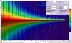
The Spectogram you show has too big of a window to get a clear look at our crossover. Personally, I like the new wavelet options in REW for that. John has added some options to make it come very close to what APL_TDA does.
APL_TDA is a very nice program to look at timing. REW now has a very similar feature, you could try that. It would be available in REW V5,19 Beta 7.
(I did not try or look to see if a newer version exists)
On the Spectogram tab, click Controls,
Choose Wavelet Mode, set Amplitude to Linear (% peak)
Resolution to 1/12 for now.
Span before peak: 4ms, Span after peak: 4 ms
Colour scheme: whatever you like (I use Rainbow)
Scale top 100%
Scale bottom 0%
You could check Normalise to peak at each frequency, as we use this for timing.
Also select Match time scale and Match top of scale and 3D enhancement.
Here's an example:

That's cheating, I don't have crossovers
That should allow us a closer look at the hand-over between tweeter and woofer.
@Michael: A first order can have the almost seamless transition of one driver to the next to keep the transient response. There is more than one way though, some of those are mentioned in this thread.
As Ben said, much has been discussed about it and for some it is something to strive for, others don't feel it's that important.
With phase manipulation we can get the same result from lots of crossover types. Many ways to get to the same point, really. RePhase is a program that can manipulate phase, separately from the frequency. At the cost of a bit of time delay in play back. DRC-FIR, Audiolense and Acourate are other options, being completely different in the way they are meant to operate.
There is much more to think about though. The off axis response for instance. Our ears will sum a larger time frame than that first wave front to determine tonal balance. So reflected energy out in a room gets into the mix we will hear. There is a big difference in perception in a room where early reflections are down by a certain amount.
The Spectogram you show has too big of a window to get a clear look at our crossover. Personally, I like the new wavelet options in REW for that. John has added some options to make it come very close to what APL_TDA does.
APL_TDA is a very nice program to look at timing. REW now has a very similar feature, you could try that. It would be available in REW V5,19 Beta 7.
(I did not try or look to see if a newer version exists)
On the Spectogram tab, click Controls,
Choose Wavelet Mode, set Amplitude to Linear (% peak)
Resolution to 1/12 for now.
Span before peak: 4ms, Span after peak: 4 ms
Colour scheme: whatever you like (I use Rainbow)
Scale top 100%
Scale bottom 0%
You could check Normalise to peak at each frequency, as we use this for timing.
Also select Match time scale and Match top of scale and 3D enhancement.
Here's an example:
That's cheating, I don't have crossovers
That should allow us a closer look at the hand-over between tweeter and woofer.
Attachments
Last edited:
I don't have the space. My lab is very cramped.
All the more reason to pick the design axis wisely. Making sure the response at larger distances follows the one that was used for measurements. As you saw, just a little time difference is enough to get an entirely different sum. As the tweeter was inverted too in this case.
For now we'll leave the influence of the room out of it. It cannot be denied though.
- Status
- This old topic is closed. If you want to reopen this topic, contact a moderator using the "Report Post" button.
- Home
- Loudspeakers
- Multi-Way
- What is Time-Alignment