There is some phase shifting going on in the last two octaves of many good Class D amplifiers. I'm not sure it is significant, but Technics has taken a brute force approach to correcting this in the digital domain using a feed-forward kind of approach.
A hobbyist using a miniDSP and the right tools could probably achieve the same thing. Certainly, Dirac would seem to do the same in the time domain.
Bet,
E
A hobbyist using a miniDSP and the right tools could probably achieve the same thing. Certainly, Dirac would seem to do the same in the time domain.
Bet,
E
These MUSO's are the V2 - I had left before they were brought out so I don't know how much they are based on the original.
ARCAM MUSO: Tough Speakers With Cuddly Corners - The Audiophile Man
I was responsible for the V1 which is the one under my name to the left, see below for another example.
ARCAM MUSO: Tough Speakers With Cuddly Corners - The Audiophile Man
I was responsible for the V1 which is the one under my name to the left, see below for another example.
Attachments
These MUSO's are the V2 - I had left before they were brought out so I don't know how much they are based on the original.
ARCAM MUSO: Tough Speakers With Cuddly Corners - The Audiophile Man
I was responsible for the V1 which is the one under my name to the left, see below for another example.
What Hi-Fi magazine reviewed the V1 and gave them 5 stars.!
Hi, Sorry I realise I have left a important factor out of the speaker design I put together; the baffle diffraction and bass alignment. If you have already bought parts let me know what you have bough and I will do my best to optimise around what you have got. If not a rework of the crossover would probably be better.
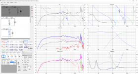
See below for a simulation of a design based on a 254 x 381 baffle (I just chose a likely size for a 8inch box if you have something specific you want let me know) I have assumed a fairly peaky base alignment as the bass is not that deep without a port and a fairly sharp turn over. I have assumed a 17L box with a port D3cm Length 7cm again if the actual port is larger (I wouldn't go much smaller) then let me know and I can recalculate its length.
Below you can see what the current crossover will do with this baffle. It affects the phase of the bass driver hence it has thrown the crossover off more than I anticipated. Also it reduces the apparent bass. So Unless the plan is to place the speaker next to a wall the response needs to be reworked to reduce the level above the bass area to match it.
Attachments
a listen to some Revel Salons told me there was a bit more work to do on the crossover
Well they probably used higher order roll-off with some tipped up treble and favorable music and electronics to fool you. Or it could be your speakers just not good.
Some unsuspecting buyers would probably have found out with his home electronics and different less than perfect recordings.
I have reworked the crossover in two variations. A minimum changes variant which retains a 4th order acoustic alignment and changes the minimum of parts to achieve the baffle step and diffraction corrected response. It does require one extra inductor to introduce the baffle step reduction but reuses the original inductor. Most of the capacitors remain the same but the resistors being the cheapest parts have been changed to adjust the response.
And
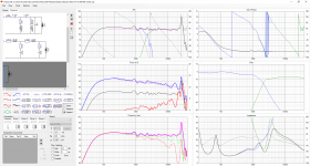
I have done a complete rework based on the fact the bass driver is aluminium and attenuating its high frequency resonance would probably be a good thing and that the tweeter is driving low so a faster cut off would reduce its use close to its LF resonance and where excursion is causing increased distortion. This is an 8th order acoustic L-R alignment using 4th order electronic circuits.
You can see this maintains better power response in the room, the speed of attention of both the bass drive and tweeter is two orders higher (24dB per octave rather than 12dB per octave) cleaning up the out of band response.
And
I have done a complete rework based on the fact the bass driver is aluminium and attenuating its high frequency resonance would probably be a good thing and that the tweeter is driving low so a faster cut off would reduce its use close to its LF resonance and where excursion is causing increased distortion. This is an 8th order acoustic L-R alignment using 4th order electronic circuits.
You can see this maintains better power response in the room, the speed of attention of both the bass drive and tweeter is two orders higher (24dB per octave rather than 12dB per octave) cleaning up the out of band response.
Attachments
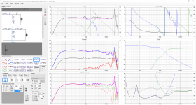
I have reworked the crossover in two variations. A minimum changes variant which retains a 4th order acoustic alignment and changes the minimum of parts to achieve the baffle step and diffraction corrected response. It does require one extra inductor to introduce the baffle step reduction but reuses the original inductor. Most of the capacitors remain the same but the resistors being the cheapest parts have been changed to adjust the response.
And
I have done a complete rework based on the fact the bass driver is aluminium and attenuating its high frequency resonance would probably be a good thing and that the tweeter is driving low so a faster cut off would reduce its use close to its LF resonance and where excursion is causing increased distortion. This is an 8th order acoustic L-R alignment using 4th order electronic circuits.
You can see this maintains better power response in the room, the speed of attention of both the bass drive and tweeter is two orders higher (24dB per octave rather than 12dB per octave) cleaning up the out of band response.
Thank you so much for taking care of it. I haven't bought the parts yet. I am thinking to sell some gears I don't use to buy the ScanSpeak drivers. I have all the data you provided me for both bass drivers, ScanSpeak and Dayton. (crossovers and cabinet internal volume) After comparing information, I am in love of the way the ScanSpeak responds (more linear, specially close to the crossover point) I am undecided of what to do. I am not sure if the final result justifies spending more money buying the ScanSpeak woofers instead of the Dayton ones. Anyway, thank you again for your time and dedication.!
I was looking to the crossover changes and the way it behaves with those new changes and have to say it is a lot better than the first simulation you did. Now, it looks closer to the ScanSpeak's response.
Last edited:
..better power response
Power response simulation would be quite accurate and useful with 10...19 off-axis measurements to 0...90/180 deg. Comprehensive polar response set would show that typical 2-way should have small hump below and dip above the crossover frequency to produce smooth power response. That shape is worth to design "blindly" if data is not adequate.
Agreed it would be much better with full off axis measurements and probably with a small bump and dip. There is a very small dip in this design. However with metal drivers I find you don't want much of a bump as the are typically already quite forward due to distortion.
I have also found typically DIY builders are unhappy to see any unevenness in the response and it is better to get them as close as you can then let them find the sweet spot between the drivers in the crossover.
Hopefully the original poster will take on board your comments and be more aware of this as an option when he gets the drivers.
Thanks, Andrew
I have also found typically DIY builders are unhappy to see any unevenness in the response..
Yes, though it is unfortunate because excessive weighting of straight axial response is the most common error in 2-way designs (diy and commercial) where woofer and tweeter do not match with directivity features of the drivers.
I'm quite hopeful that measurement and design methods are improving, and inadequate design by single axial/reference angle only will fade away. Tradition of bad design is strong but hopefully we can beat it.
I would think so. Many customers of commercial speakers probably don't realise these limitations, might not buy a good acoustic design, and might not know how to use them if they did.. Now there's a challenge.excessive weighting of straight axial response is the most common error in 2-way designs (diy and commercial) where woofer and tweeter do not match with directivity
One essential thing is that axial response doesn't have to be crap in order to reach good power response and off-axis responses in horizontal plane. Speaker can be optimized by all of those simultaneously. Sometimes all errors cannot be perfectly eliminated but location and +/- magnitude of the errors remain valuable for the total - not mirrored and/or poorly located which is possible by optimizing simply by the axial response.
Yes, though it is unfortunate because excessive weighting of straight axial response is the most common error in 2-way designs (diy and commercial) where woofer and tweeter do not match with directivity features of the drivers.
I'm quite hopeful that measurement and design methods are improving, and inadequate design by single axial/reference angle only will fade away. Tradition of bad design is strong but hopefully we can beat it.
I was totally unaware of it. However, I would like to know what practical results can we expect if we chose an straight axial response ?? I am thinking of a difficult driver blend around the crossover region but I don't have any idea how it could be translated to the final sound of the speakers. Also, what is the benefit of having an small hump below and a dip above the crossover frequency ?? Only an smooth power response ?? Is there any negative effect of it ?? I really was looking to the linearity of the response and thought it was a goal when designing. Thanks for your participation and tips.!
Agreed it would be much better with full off axis measurements and probably with a small bump and dip. There is a very small dip in this design. However with metal drivers I find you don't want much of a bump as the are typically already quite forward due to distortion.
I have also found typically DIY builders are unhappy to see any unevenness in the response and it is better to get them as close as you can then let them find the sweet spot between the drivers in the crossover.
Hopefully the original poster will take on board your comments and be more aware of this as an option when he gets the drivers.
Thanks, Andrew
You are right.! I was looking to the sweetest blend between the drivers in the crossover range thinking it will translate in a better sound. I am aware of the limitations and compromises that affects it but didn't know there is a way of "compensate" it and it isn't an straight response. What do you think about the first simulation you did using the ScanSpeak bass driver ?? Do you still believe it is a better match for the Peerless dome tweeter ?? Thank.!
Last edited:
You can see how hard it is to do a smooth transition between drivers, that's why many diyers chose other options which are far from the mainstream, though they don't have to be
Yes, you see full range designs and open baffles more than anything.
It is for that reason that I drove the tweeter as low as a dared as the tweeter has good off axis response and the higher you use the woofer the worse the transition from the poor woofer off axis response to the excellent tweeter off axis response is.
What this causes is poor overall response in the room as your ear hears quite a lot of the energy reflected off the walls floor and celling as well as the direct on axis response.
For this particular aspect of the design the difference between the Scan Speak and the Dayton is not easy to compare, as pointed out the manufacturers data only gives very sparse information off axis and the Scan Speak and Dayton drivers give it at different points (the scan speak goes out to 60 Deg whilst the Dayton only gives 45 Deg) so its hard to compare the designs directly.
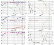
I have marked up a diagram and can talk though some of the compromises we could make too the axial response to improve the in room response.
The purple area is where you typically want a bit of a hump especially with a low distortion driver. This is to fill in the dip in the power response you can see its effect on the directivity index (it causes a hump circled in red). Another approach to this which I used to some extent is to compromise the roll off on the tweeter so it extends into the poor off axis part of the woofer response filling it in, however this is only possible if the phase can be maintained.
The other area circled in red on the directivity graph and blue on the axis response is where the tweeter is becoming dominant and the energy in the room will rise due to its much better off axis response. Typically you want a bit of a dip here. I haven't done that here partly as mentioned it rarely goes down well and partly as I put this together as an example rather than a full development, as I mentioned I anticipated you would want to adjust it by listening.
If you want to go with the Scan Speak Design, I can go back and do a more thorough theoretical approach but as mentioned really you need the measurements of the real driver in the real cabinet at many off axis points to get a good assessment of the power response in the room. To get a good approximation I would also need the dimensions of the cabinet you plan to use. You can also of course adjust this by ear, so long as you only more in relatively small steps and look at what you are doing by reviewing how the change changes the simulation.
Sorry if this is all a bit confusing there are a lot of competing compromises to factor in when designing a speaker.
What this causes is poor overall response in the room as your ear hears quite a lot of the energy reflected off the walls floor and celling as well as the direct on axis response.
For this particular aspect of the design the difference between the Scan Speak and the Dayton is not easy to compare, as pointed out the manufacturers data only gives very sparse information off axis and the Scan Speak and Dayton drivers give it at different points (the scan speak goes out to 60 Deg whilst the Dayton only gives 45 Deg) so its hard to compare the designs directly.
I have marked up a diagram and can talk though some of the compromises we could make too the axial response to improve the in room response.
The purple area is where you typically want a bit of a hump especially with a low distortion driver. This is to fill in the dip in the power response you can see its effect on the directivity index (it causes a hump circled in red). Another approach to this which I used to some extent is to compromise the roll off on the tweeter so it extends into the poor off axis part of the woofer response filling it in, however this is only possible if the phase can be maintained.
The other area circled in red on the directivity graph and blue on the axis response is where the tweeter is becoming dominant and the energy in the room will rise due to its much better off axis response. Typically you want a bit of a dip here. I haven't done that here partly as mentioned it rarely goes down well and partly as I put this together as an example rather than a full development, as I mentioned I anticipated you would want to adjust it by listening.
If you want to go with the Scan Speak Design, I can go back and do a more thorough theoretical approach but as mentioned really you need the measurements of the real driver in the real cabinet at many off axis points to get a good assessment of the power response in the room. To get a good approximation I would also need the dimensions of the cabinet you plan to use. You can also of course adjust this by ear, so long as you only more in relatively small steps and look at what you are doing by reviewing how the change changes the simulation.
Sorry if this is all a bit confusing there are a lot of competing compromises to factor in when designing a speaker.
Attachments
Below is an example of a design I am looking at where you can see an example of an improved theoretical response. It is of a 5.5inch and a ring radiator tweeter which makes the integration much easier however there is still a region where the tweeter is slightly dominant. This has no cabinet effects included I was just looking at how the drivers would match.
Attachments
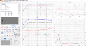
Below is an example of a design I am looking at where you can see an example of an improved theoretical response. It is of a 5.5inch and a ring radiator tweeter which makes the integration much easier however there is still a region where the tweeter is slightly dominant. This has no cabinet effects included I was just looking at how the drivers would match.
It is a lot better with those drivers. However, 5.5" or 6" woofers don't work for me. I can not listen to the music at the level I normally do with small drivers. I don't have too much space either to think about a 3 way design using 10" woofers. (I assume 3 way designs still have compromises) I can think about a 3 way design such as a large bookshelf. If it will be a better option, I can consider it. At the end, what I want is bookshelf size speakers (not necessary too small) with an 8" woofer. See an example below:
yamaha bookshelf speakers - Google Search
I like the size of those Yamaha NS-6490. They use an 8" woofer inside a sealed enclosure. Something like this will be perfect for me. ( with good drivers and crossovers)
Last edited:
- Status
- This old topic is closed. If you want to reopen this topic, contact a moderator using the "Report Post" button.
- Home
- Loudspeakers
- Multi-Way
- DIY vs brand speaker