Most 2.5 way TMM crossovers I have seen involve a parallel configuration of 8 ohm woofers with the upper woofer crossing over to the tweeter and the lower woofer rolled off at a lower frequency, acting more as compensation below the baffle step frequency.
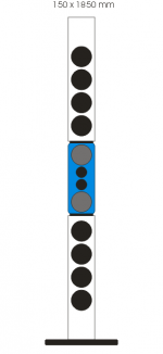
I have become very curious about the recent designs employing 3 woofers such as the Elac towers. I have not seen the topography of these crossovers but from specs, I suspect the 3 woofers are 4 ohm wired in series, with a bypass capacitor across the 2 lower woofers to leave only the upper woofer as the midrange. The woofers would then cross over to the tweeter in a conventional parallel network.
For this configuration, voltage sensitivity would be the same as one driver, but efficiency quite higher due to the reduction of the current and therefore power for the same output. Response would also be the same as one woofer. The bypass capacitor, while reducing voltage to the 2 lower woofers would provide a corresponding increase to the upper woofer as frequency increases.
Has anyone tried this?
I haven't but I plan to do something in that sense. I have decided that the price per midwoofer should be in the 5€ range and twice as much for tweeters. The timber will probably be chipboard 12 mm, braced decently. The crossover passive, Linkwitz Transform to EQ the woofers up until F3=45Hz. About finish I'll brainstorm once it's voiced to my satisfaction.
Attachments
Last edited:
At low frequencies, all three woofers would share the load equally because their impedance is the same. As the frequency increases, the bypass capacitor reduces the impedance across the lower 2 shifting all the load to the upper one. The upper woofer would handle all the upper mids and 1/3 of the lowest bass with a gradual shift in between. I believe this is what Andrew Jones is doing in the Elac F5 and F6 and others. I would love to verify that.
Not really. There is no increase in output when drivers wired in series. There is three times the radiating area but each speaker sees one third of the voltage and one third of the current. The SPL output for the same amplifier voltage is the same as one driver.Three woofers vs one will give you greater than +6dB difference, maybe 3 v 2 would work better.
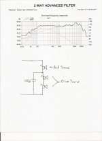
This is the circuit I am talking about. This is a simple parallel LR2 at 2-3 KHz with the 3 bass drivers operating at low frequencies but the lower 2 rolled off by C2 at increasing frequencies. The High crossover could be anything else such as LR4 or BW3
Three 5.25" bass drivers would have the radiating area of One large 8"driver.
Three 6.5" bass drivers would have the radiating area of one 11" driver.
Combined woofer output would be similar to one driver for the same Voltage input (not power).
This configuration has no natural baffle step compensation. It would have to be provided by L1 or an additional shelving network.
I strongly suspect this may be behind the new Elac towers.
Attachments
I have not seen the Sonus Faber design.
Some very good low distortion 5.25" woofers this design may work with:
Scan speak 15W/4524T Special Edition
SB15NBAC30-4 aluminum cone
I have modeled these in LSPcad and they wind up with a mild extended bass shelf alignment to get a decent F3. I am going to model 3 Satori MW16P-4s to see how they would work. The thought of a 360 square cm radiating surface with the mid quality of the Satori would be enticing.
I am not sure what the Elacs' configuration looks like, but I have had this design in the back of my mind for a few years and I am wondering if they are doing this.
I am sure the configuration works electrically. I have modeled the three woofers in series with the bypass capacitor across 2 and it worked just as predicted. I have also played with adding a very small resistor in series with the bypass cap.
I currently have 2 of the Scan 15W4524T drivers and with the $49 sale price, am toying with the idea of getting 4 more to try this. I like the concept of having the upper response and directivity of a 5" driver with 240 sq cm of bass radiating area, and with only a little more complication than a 2 way LR2.
The specs of the Elac speakers, (6 ohms and 100Hz - 3 KHz crossovers) make me suspicious. When I model this circuit I get around 6 ohms in the mid-range. I also doubt that a budget speaker would include an enormous inductor for a conventional 100 Hz crossover. The bypass cap does this very inexpensively, and even though large, no super device is needed for this service. You can spend the money on the tweeter cap.
Maybe I failed to make my point that if you are using this to compensate your baffle you might choose a level equal to or less than +6dB.Not really. There is no increase in output when drivers wired in series. There is three times the radiating area but each speaker sees one third of the voltage and one third of the current. The SPL output for the same amplifier voltage is the same as one driver.
I still do not get your point. I am not using this to compensate for baffle step. Connecting woofers in series does not increase output for a given voltage signal input. Unlike a parallel connection, there is no +6 dB output difference when you double drivers, or +9 dB if you triple them. With this, baffle step has to be compensated in the traditional way, through increasing the L value or using a shelving network. In a way it is more flexible than a parallel connection where you would actually be locked to 9 dB of compensation if you used 3 woofers and rolled off the lower 2. Here you can design for only the compensation needed based on placement.Maybe I failed to make my point that if you are using this to compensate your baffle you might choose a level equal to or less than +6dB.
The attached graph from LspCad shows the SPL distribution among the woofers with a 100uf bypass capacitor. The blue trace is the combination of the lower woofers. The red trace is the upper woofer/mid. The black trace is the summed response. These are for a Scan Speak 15W/4524T Limited Edition in an IEC baffle (manufacturer data)
You can see that above 300 Hz or so, the upper driver completely takes over. Changing the capacitor value shifts the point where the lines diverge but the summed output always stays the same. Adding a 1 ohm resistor in series with the capacitor levels out the blue trace between 70 and 75 dB.
This also looks very promising for a trio of Satori MW16P-4 in a 50 liter enclosure as well as three SB17NBAC35-4 Aluminum cone woofers also in 50 liters.
Attachments
I can see how a lower sensitivity upper driver would help compensate for the baffle step but when you wire drivers in series it is normally recommended that they be identical so there are no major impedance differences to complicate the summation. I would probably stick with identical drivers and deal with the baffle step in the network.
What is your variant?
What is your variant?
Re:'What is your variant? ' - 3 way series, so there's a cap across the 'upper woofer'/mid as well...
I was just using up some old drivers I had lying around taking up too much space, so wasn't looking for great accuracy, but the result was great, so built another set using the same topology
I was just using up some old drivers I had lying around taking up too much space, so wasn't looking for great accuracy, but the result was great, so built another set using the same topology
- Status
- This old topic is closed. If you want to reopen this topic, contact a moderator using the "Report Post" button.
- Home
- Loudspeakers
- Multi-Way
- 2.5 Way Crossovers