Loudspeakers are the most nonlinear elements in the whole audio reproduction chain and there are numerous ways to reduce their nonlinearity (as stated for example by Klippel here), including adoption of different types of acoustic, motion or electric feedback or machine learning. The most obvious and easiest to implement seems to be employment of current control instead of usual voltage control to drive the speakers. While trying to quantify the difference, I have written some MATLAB/Octave scripts aimed to automate and speed up comparative measurements of harmonic and intermodulation distortion of a speaker with VC and CC, which I would like to share with you along with my results.
There are a few pitfalls in performing these measurements which must be taken care of, mainly the distortion of a measurement microphone, which is able to totally plague the results. Common electret microphones are unusable due to nonlinearity of a built-in JFET, unless you use them with a circuit that compensates for it. I've described it along with my scripts on a separate page: Measurements of nonlinear distortion
Another issue is a different amplitude characteristic you get with voltage and current drive due to non-constant impedance of the drivers. It is not possible to compare the results obtained with constant current and constant voltage, because the power the driver receives varies with frequency differently in each case due to its varying impedance. This is why my scripts take a feedback from the microphone and use it to normalize the measurements for a constant SPL.
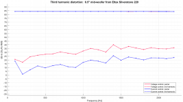
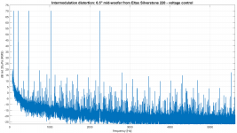
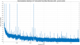
I would like to regularly post measurements of every speaker within my reach, including both cheap and expensive drivers and also modern and vintage ones. For each driver, I will post a third harmonic vs. frequency and IMD measurements comparing voltage and current mode of operation.
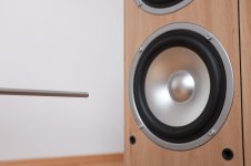
First one is a paper cone, rubber surround 6.5" mid-woofer from the Eltax Silverstone 220 budget speakers.
There are a few pitfalls in performing these measurements which must be taken care of, mainly the distortion of a measurement microphone, which is able to totally plague the results. Common electret microphones are unusable due to nonlinearity of a built-in JFET, unless you use them with a circuit that compensates for it. I've described it along with my scripts on a separate page: Measurements of nonlinear distortion
Another issue is a different amplitude characteristic you get with voltage and current drive due to non-constant impedance of the drivers. It is not possible to compare the results obtained with constant current and constant voltage, because the power the driver receives varies with frequency differently in each case due to its varying impedance. This is why my scripts take a feedback from the microphone and use it to normalize the measurements for a constant SPL.
I would like to regularly post measurements of every speaker within my reach, including both cheap and expensive drivers and also modern and vintage ones. For each driver, I will post a third harmonic vs. frequency and IMD measurements comparing voltage and current mode of operation.
First one is a paper cone, rubber surround 6.5" mid-woofer from the Eltax Silverstone 220 budget speakers.
Attachments
Interesting work. I tried something similar, about 3 years ago:
Current drive of speakers and speaker distortion
Current drive of speakers and speaker distortion
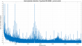
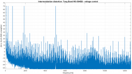
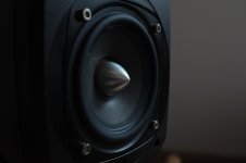
Next tested speaker is Tang Band W3-594SB, a 3" full range driver with a paper cone and aluminium phase plug boasting an underhung design. Because of that, I expected it to have lower distortion that the previous no name driver, but it turned out to be pretty similar in that regard.
X-max is only 0.4 mm, which was probably exceeded during measurement of harmonic distortion at low frequencies, but I still wanted to keep the same SPL for all the drivers to allow for mutual comparison.
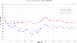
With voltage control, 3rd harmonic distortion peaks at 2.9kHz being 39dB bellow the carrier. With current control, this peak is lowered to somewhere around 60dB bellow the carrier.
Above 1kHz, 3rd harmonic distortion with current control was reduced by about 15-20dB compared to voltage drive. Interestingly, at 100Hz and 300Hz the situation gets different and the distortion with current control is higher than with voltage control. This showed up in the IMD measurement too, where 2nd harmonic of lowest tone (100Hz) has risen by some 12dB with current control.
Datasheet: https://www.parts-express.com/pedocs/specs/264-814-tang-band-specifications-45649.pdf
X-max is only 0.4 mm, which was probably exceeded during measurement of harmonic distortion at low frequencies, but I still wanted to keep the same SPL for all the drivers to allow for mutual comparison.
With voltage control, 3rd harmonic distortion peaks at 2.9kHz being 39dB bellow the carrier. With current control, this peak is lowered to somewhere around 60dB bellow the carrier.
Above 1kHz, 3rd harmonic distortion with current control was reduced by about 15-20dB compared to voltage drive. Interestingly, at 100Hz and 300Hz the situation gets different and the distortion with current control is higher than with voltage control. This showed up in the IMD measurement too, where 2nd harmonic of lowest tone (100Hz) has risen by some 12dB with current control.
Datasheet: https://www.parts-express.com/pedocs/specs/264-814-tang-band-specifications-45649.pdf
Attachments
Happy new year everyone,
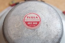
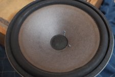
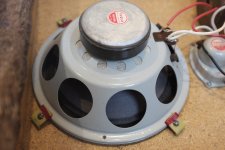
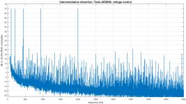
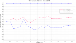
I have a piece of history here - ARZ669, an 8" woofer made by Czechoslovakian state-owned company Tesla (nothing to do with the carmaker) between the years 1966 and 1974.
There were many variations through the production period and the speaker later evolved into models ARN664, ARN6604 and until recently produced ARN226 with declining reputation. I reckon this unit was probably made around 1970, however, it is in pristine condition (apart from a faded paper).
There is no datasheet, but the manufacturer specified the free-air resonant frequency to be 25Hz and maximum continuous input power to be 5W.
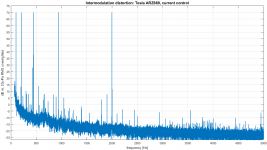
So how did this almost 50 years old driver do? With a voltage drive, the 3rd harmonic distortion was worst at 1300Hz (38dB bellow the carrier), but generally it was around 40-45dB bellow the carrier. When switched to the current drive, the distortion dropped by 20dB-30dB, apart from the bellow-200Hz region, where the improvement is only slight (4dB) and a significant peak that remained at 600Hz only 6dB bellow original value, which hints some mechanical issues. The difference looks even more dramatic in the IMD measurement spectrum. The only distortion component that remained relatively unchanged is the one at 422Hz, which is the second harmonic of the second-lowest test tone (211Hz).
There are more information about this driver (and also measured T-S parameters) on this site:
ReproMania.NET | Tesla | Reproduktory basove | ARZ 669
I have a piece of history here - ARZ669, an 8" woofer made by Czechoslovakian state-owned company Tesla (nothing to do with the carmaker) between the years 1966 and 1974.
There were many variations through the production period and the speaker later evolved into models ARN664, ARN6604 and until recently produced ARN226 with declining reputation. I reckon this unit was probably made around 1970, however, it is in pristine condition (apart from a faded paper).
There is no datasheet, but the manufacturer specified the free-air resonant frequency to be 25Hz and maximum continuous input power to be 5W.
So how did this almost 50 years old driver do? With a voltage drive, the 3rd harmonic distortion was worst at 1300Hz (38dB bellow the carrier), but generally it was around 40-45dB bellow the carrier. When switched to the current drive, the distortion dropped by 20dB-30dB, apart from the bellow-200Hz region, where the improvement is only slight (4dB) and a significant peak that remained at 600Hz only 6dB bellow original value, which hints some mechanical issues. The difference looks even more dramatic in the IMD measurement spectrum. The only distortion component that remained relatively unchanged is the one at 422Hz, which is the second harmonic of the second-lowest test tone (211Hz).
There are more information about this driver (and also measured T-S parameters) on this site:
ReproMania.NET | Tesla | Reproduktory basove | ARZ 669
Attachments
Happy new year! Very nice thread here.
Yes. Also some modern drivers have cone/edge resonances which will show high distortion regardless of transition to current control, but generally motor-based nonlinear distortion dives especially with non-conductive voice coil former.
..significant peak that remained at 600Hz only 6dB bellow original value, which hints some mechanical issues.
Yes. Also some modern drivers have cone/edge resonances which will show high distortion regardless of transition to current control, but generally motor-based nonlinear distortion dives especially with non-conductive voice coil former.
I read a few articles about the advantages of current drive, and the arguments in favour of it seemed pretty sound for all frequencies far from resonance. However, quite close to resonance (at the impedance peak or peaks) you could argue that with voltage drive, the back-EMF acts as a kind of motional feedback, reducing distortions related to the transfer from force to acceleration.
You sometimes see that voltage drive works better than current drive at low frequencies. Do you see any relation between that and the resonance frequency of the loudspeaker?
You sometimes see that voltage drive works better than current drive at low frequencies. Do you see any relation between that and the resonance frequency of the loudspeaker?
Nice data. You should plot your frequency response graphs with a log scale on the frequency axis, it is more intuitive IMO.
Another thing to consider is the usable frequency range of the driver. Running low frequency tones on a small 3" driver is going to swamp the result with spurious tones as it can't deal with the excursion. Similarly a larger driver like a 6.5" is going to have trouble with IMD due to Le(x) when you run low frequency tones along with tones above the electrical lowpass frequency of the voicecoil f=(Re/(2*pi*Le)). Much of the reduction in distortion when using current drive is from eliminating the amplitude modulation caused by Le(x). If you use the driver over a bandwidth that minimises the effect of the Le(x) limitation of the driver - not pushing the driver to excursion limits and not using the driver at frequencies where it's inductive, then voltage drive isn't so bad.
Another thing to consider is the usable frequency range of the driver. Running low frequency tones on a small 3" driver is going to swamp the result with spurious tones as it can't deal with the excursion. Similarly a larger driver like a 6.5" is going to have trouble with IMD due to Le(x) when you run low frequency tones along with tones above the electrical lowpass frequency of the voicecoil f=(Re/(2*pi*Le)). Much of the reduction in distortion when using current drive is from eliminating the amplitude modulation caused by Le(x). If you use the driver over a bandwidth that minimises the effect of the Le(x) limitation of the driver - not pushing the driver to excursion limits and not using the driver at frequencies where it's inductive, then voltage drive isn't so bad.
Last edited:
TMM: Yes, 100Hz was probably too low for the IMD measurement of the Tang Band fullrange. However, the 6.5" driver comes from a 2-way system, so measurement range of 100-2200Hz was within it's normal operating region. Also these five tones were at 70dB SPL @ 30cm (1ft) each, which isn't too loud. The power input was in region of hundreds of mW.
MarcelvdG: There was an article on Audioxpress.com, a review of a book on current drive by Esa Meriläinen, where they also measured a speaker in the bass region and got worse result with the current drive. The author of a book commented on that in a following way:
The other factor might be that because of higher excursion at low frequencies, the mechanical distortion products are higher and might partially cancel out the motor distortion products at certain frequencies with the voltage drive.
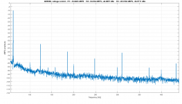
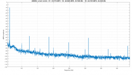
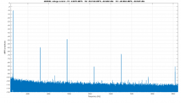
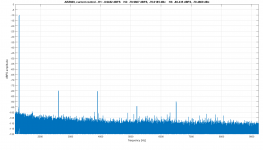
I was curious what the situation was so I measured Tesla ARZ669 woofer at the resonant frequency (62Hz). I also measured spectrum at 1300Hz, where the difference in the H3 distortion was the most prominent. Don't mind the y axis, the SPL is still the same as in the previous H3 measurements: 84dB @ 30 cm.
MarcelvdG: There was an article on Audioxpress.com, a review of a book on current drive by Esa Meriläinen, where they also measured a speaker in the bass region and got worse result with the current drive. The author of a book commented on that in a following way:
Concerning Fig. 13, lowering the mechanical Q is indeed key to control this kind of distortion; but it is also noteworthy that the driver was mounted in a very large enclosure (I was told 95 ltr) and without proper stuffing, so the system is operating at the mercy of the driver's own nonlinear spring force and damping force. Both of these can be linearized considerably with a proper size cabinet and effective use of damping material (and driver optimization).
"It seems that the reverse current generated by spurious cone movement "distorted" the voltage drive net current in such a way as to correct some of the distortion."
This is the partial velocity feedback effect that occurs within an octave or so from the resonant point but is ineffective elsewhere, where the EMF current is smaller and perpendicular to the signal applied.
Obtained from here
The other factor might be that because of higher excursion at low frequencies, the mechanical distortion products are higher and might partially cancel out the motor distortion products at certain frequencies with the voltage drive.
I was curious what the situation was so I measured Tesla ARZ669 woofer at the resonant frequency (62Hz). I also measured spectrum at 1300Hz, where the difference in the H3 distortion was the most prominent. Don't mind the y axis, the SPL is still the same as in the previous H3 measurements: 84dB @ 30 cm.
Attachments
- Status
- This old topic is closed. If you want to reopen this topic, contact a moderator using the "Report Post" button.
- Home
- Loudspeakers
- Multi-Way
- Nonlinear distortion measurements of loudspeakers - voltage and current control