Please, is it less good to use a non polar cap for a Zobel or smoothing impedance LCR? Or is it important to stay with bipolar caps in // with the drivers when it comes to correct the impedance curve of a speaker ? Why bipolar might be mandatory here ? Less ESR or less ESL ?
Asked because soimetimes the shunted capacitance value can be huge : 600 uF, 400 uF.
If a bipolar cap is mandatory there: could two good 105 °C elec caps in reverse (+--+) make the trick please (despite the thin leads of circuits elec caps) ? Or will it be never as good as a standalone bipolar elec cap ?
And if I may : Can we get down ESR in an initialy speaker filter designed with elec caps without moving the XO between the drivers (swapping elec caps by film foil caps : serie and shunt?)
Multi thanks
Please, is it less good to use a non polar cap for a Zobel or smoothing impedance LCR? Or is it important to stay with bipolar caps in // with the drivers when it comes to correct the impedance curve of a speaker ? Why bipolar might be mandatory here ? Less ESR or less ESL ?
Asked because soimetimes the shunted capacitance value can be huge : 600 uF, 400 uF.
If a bipolar cap is mandatory there: could two good 105 °C elec caps in reverse (+--+) make the trick please (despite the thin leads of circuits elec caps) ? Or will it be never as good as a standalone bipolar elec cap ?
Electrolytic caps are either polarized, or non polarized. In DC circuits, polarized is acceptable, but speakers are AC, so you must use bi-polar or put a pair of polar's back to back:
--||--||-- where they are connected in the middle by the same polarity. This is fine, but you need 4x the total uF. That is, if you need 10uF, you end up using 2 x 20uF.
Film caps are all non-polars that's another option.
And if I may : Can we get down ESR in an initialy speaker filter designed with elec caps without moving the XO between the drivers (swapping elec caps by film foil caps : serie and shunt?)
Multi thanks
Going from a high ESR cap to very low ESR (1 Ohm to < 0.3) can have unexpected consequences. Modern electrolytics are more consistent, and more consistently lower ESR.
If you can measure the ESR, you can compensate for this by adding a resistor. In this example above, you could add about 0.7 Ohms in series to make up the difference.
Last edited:
Polarized caps will ( actually ) work ( for a while ) within an AC circuit ( when the AC going through them is kept below 1 volts ).
As a result of that limitation they are not realistic for real world use within a network for speakers ( unless one adds a DC bias to the network ) .
It's not commonly understood that the electrolytics within the polarized capacitor "requires" a polarized DC voltage to function properly (ie; energize the electrolytics ).
That's why these caps are commonly found in AC circuits within audio gear ( acting as DC blockers where the presence of DC is actually paramount to the polarized caps long-term survival ).
Feed a polarized cap too much AC voltage and it will blow up ( when DC is not present to keep some of its Voltage capacity, polarized ).
Feed a polarized cap the wrong polarity of DC ,, & it will blow up.
This info is all available through Google ( with accompanying YouTube videos about blowing them up ).
It's easy enough to study the real-world filtering effects of polarized caps within AC circuits ( ie; inserting them into a passive speaker network and then measuring the filters effects is easy to do > >> just keep the drive voltage below 1 volt ).
")
As a result of that limitation they are not realistic for real world use within a network for speakers ( unless one adds a DC bias to the network ) .
It's not commonly understood that the electrolytics within the polarized capacitor "requires" a polarized DC voltage to function properly (ie; energize the electrolytics ).
That's why these caps are commonly found in AC circuits within audio gear ( acting as DC blockers where the presence of DC is actually paramount to the polarized caps long-term survival ).
Feed a polarized cap too much AC voltage and it will blow up ( when DC is not present to keep some of its Voltage capacity, polarized ).
Feed a polarized cap the wrong polarity of DC ,, & it will blow up.
This info is all available through Google ( with accompanying YouTube videos about blowing them up ).
It's easy enough to study the real-world filtering effects of polarized caps within AC circuits ( ie; inserting them into a passive speaker network and then measuring the filters effects is easy to do > >> just keep the drive voltage below 1 volt ).
Last edited:
Thanks, very informative.
Can I know the ESR starting from the angle loss specs ? The speaker was made more than 30 years ago, I assume I can't measure the genuine specs anymore and haven't specific Tools. But I know the speaker in brandnew condition had caps with 5% at 1 K Hz loss angle for some marked Low Loss and 10% for the others ! For instance is it equal for the 5% to 0.005 ESR at 1 K Hz we can see in some datasheets ! (my basic understanding is the loss angle is not only a part of ESR but ESL as well) ?
Can I know the ESR starting from the angle loss specs ? The speaker was made more than 30 years ago, I assume I can't measure the genuine specs anymore and haven't specific Tools. But I know the speaker in brandnew condition had caps with 5% at 1 K Hz loss angle for some marked Low Loss and 10% for the others ! For instance is it equal for the 5% to 0.005 ESR at 1 K Hz we can see in some datasheets ! (my basic understanding is the loss angle is not only a part of ESR but ESL as well) ?
Thanks, very informative.
Can I know the ESR starting from the angle loss specs ? The speaker was made more than 30 years ago, I assume I can't measure the genuine specs anymore and haven't specific Tools. But I know the speaker in brandnew condition had caps with 5% at 1 K Hz loss angle for some marked Low Loss and 10% for the others ! For instance is it equal for the 5% to 0.005 ESR at 1 K Hz we can see in some datasheets ! (my basic understanding is the loss angle is not only a part of ESR but ESL as well) ?
Short answer > I don't remember how to extrapolate ESR from phase angle changes ( though I'm sure there's a formula in one of my Electronic Math Books ) .
- I do know that last week I took a pair of 40 year old 3uF polarized electrolytic caps > put them into a speaker network and the expected driver output fell, something like 4 db .
Obviously these ancient polarized caps had built-up a lot of ESR over the last 40 years .
My advice ( if playing around with expensive vintage gear ) buy some appropriate measuring equipment ( if ESR is that critical to your networks performance ).
Those are extremely large value capacitors >>> how are they being used & in what type of speaker ?
I'd likely buy some polarized caps ( at twice the needed value ) , attach the negate ends together and then feed the junction of the 2 caps some DC ( from a 9V battery > or 2 AA batteries ). If that part of the circuit needed more resistance, then I would add a resistor inline to those back-2-back caps.
Last edited:
tricky this resistor between the two caps to increase the ESR
well yes the angle loss seems important when I see a cap as high than 450 uF with only 0R68 in serie to the ground !
Big values are involved in the bass section and a part of impedance network correction ! If interrested I have opened a thread in the Parts section !
I wanted firstly to putt mylar in spite of the elec caps, at least for serie caps in mid & treble sections ! I don't like basic MKP sound but the true copper foilded I can not afford. think even Mylar have a much lower ang loss and ESR than the Alcap elec bipolar rated at 5% angle loss !
I could purchase an expensive re cap kit from Falcon Acoustic with more or less the same caps than the genuine but I had hope for better serie caps... But if the said beter dielectric breaks the design here and sounds worse, I'd prefer avoid !
tricky this resistor between the two caps to increase the ESR
well yes the angle loss seems important when I see a cap as high than 450 uF with only 0R68 in serie to the ground !
Big values are involved in the bass section and a part of impedance network correction ! If interrested I have opened a thread in the Parts section !
I wanted firstly to putt mylar in spite of the elec caps, at least for serie caps in mid & treble sections ! I don't like basic MKP sound but the true copper foilded I can not afford. think even Mylar have a much lower ang loss and ESR than the Alcap elec bipolar rated at 5% angle loss !
I could purchase an expensive re cap kit from Falcon Acoustic with more or less the same caps than the genuine but I had hope for better serie caps... But if the said beter dielectric breaks the design here and sounds worse, I'd prefer avoid !
Sorry, that's not what I meant ( re; putting the resistor between the 2 caps > that would unbalance the DC supply to the 2 caps via being a voltage divider ) .
I was implying ( obviously not being clear enough ) to put the resistor outside of the 2 cap bundle .
Obviously, a cap going to ground will eventually ( based on the value of the cap ) start feeding/shorting HF to ground.
How & when this action needs to happen is part of the circuit design ( & will include some necessary resistance so that the amp-source never-ever sees a dead short ).
Asked because sometimes the shunted capacitance value can be huge : 600 uF, 400 uF.
Do you have an example of where a zobel calculator is asking for that large a cap?
Well, not a Zobel with those values, a complex LCR perhaps (sort of Zobel after a LCR & // to it ?! I never saw that before.
these guys at Kef made complex filters. Or perhaps a part of a low pass filter >= second order in bass section . Which is not clear as I don't see (know) why a low pass filter would have to shunt a resistor, 2 coils and caps (450 u & 600u), all in serie towards the ground (shunt).
the max capacitance value I see which looks like a zobel (CR // to the drivers) is a 25 uF but again the network is complex so not sure of that !
Anyway I know now all these caps must be bipolars and angle loss near or equal to the previous caps in order not to waste the original design.
thanks for that
Apparently, the speaker in question here is a KEF 104/2 ( & the desire is to recap it ) .
Here's one internet offering of it's network.
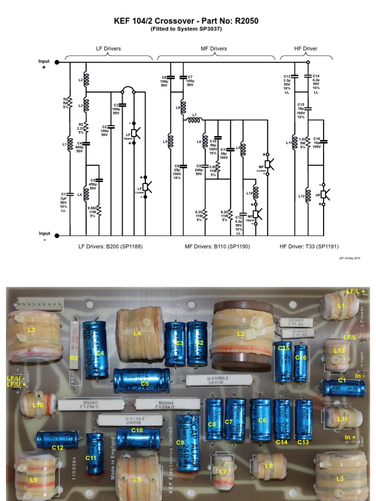
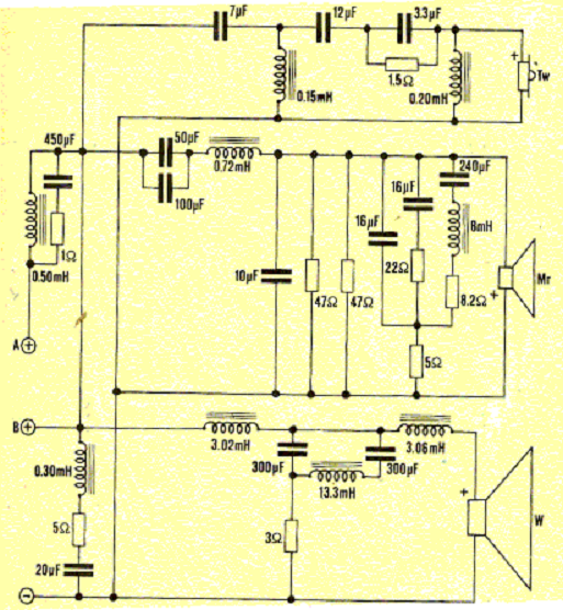
At first I was reluctant to believe the accuracy/veracity of any document showing such large cap values within a network ( while hiding the coil values ), but after reviewing the following KEF C80 schematic most of those doubts have dissipated.
Yes, it looks like KEF used huge value capacitors.
I'd be very cautious when deciding to recap a network such as this / starting with a single section of drivers ( & then listening for a month ) to see if I like the changes.
With this many capacitors present //there's many more ways to make the speaker's voicing worse.
Here's one internet offering of it's network.
At first I was reluctant to believe the accuracy/veracity of any document showing such large cap values within a network ( while hiding the coil values ), but after reviewing the following KEF C80 schematic most of those doubts have dissipated.
Yes, it looks like KEF used huge value capacitors.
I'd be very cautious when deciding to recap a network such as this / starting with a single section of drivers ( & then listening for a month ) to see if I like the changes.
With this many capacitors present //there's many more ways to make the speaker's voicing worse.
An externally hosted image should be here but it was not working when we last tested it.
An externally hosted image should be here but it was not working when we last tested it.
An externally hosted image should be here but it was not working when we last tested it.
Attachments
Last edited:
Wow, that's a complex crossover. They either tried to remedy some misbehaving drivers or tried to achieve some specific sound.
I always try to use well behaving drivers and first order filters to have flat phase response together with fr response. Simple crossover sounds better to me.
Complex crossovers may solve on axis response, but mess up something else down the road.
I always try to use well behaving drivers and first order filters to have flat phase response together with fr response. Simple crossover sounds better to me.
Complex crossovers may solve on axis response, but mess up something else down the road.
Seems the few choices I have is to purchase a Falcon Acoustic recap set !
But all the 50V caps are swaped by 100V caps in this recaping kit My understanding is the use of 50V was also because it gives a different sounding result than 100 v : tighter/sharper sounding presentation ! Maybe it was just because they are littlier on the pcb but the mix between the 50v and 100V looks like more a design choice !
Hard to restore such complex networks ! Sure restoration of both aesthetical cabinet and sound may be wasted ! Some caps values are not very standards in elec bipolars family...
Last edited:
I know someone who recapped some 104's and disliked the speakers after doing it.
Large caps in impedance peak filters are necessary. You can spend $50-100 on a big film cap, or just add some small film bypass caps.
does it really work, or is there not an ESR mismatch between the ESR of the elec and the ESR of the little film cap (if MKP) bypassing value ... giving an uncertain result at ears... I'm suspicious with bypassing...almost when the values are low like 0.1 uF side to side caps with big capacitance...50 uF...600 uF, oups !
Seems these guys at Kef played with the Z of the caps to acheive specific results ?! Look at the mid of the kef 104/2 above : two 100 uF 50V without resistor for spl matching... they are right there at the level they wanted and they use two 100 uF/50V in // to divide the ESR in spite of a 200 uF from an other voltage...
A suggestion ( rather than just talking about ESR theory );
Buy some replacement Alcaps from someone like this British eBay seller in some values that are found in your speakers.
- I think I'd buy the 100uF size.
Also, buy yourself a regular capacitance meter and another meter that can measure ESR.
Once you have all these parts ( & meters ) on hand >> measure the new caps and compare them to your older Alcaps.
You may just find that the older Alcaps are still in spec.
Read this Parts Express customer testimonial > near the page bottom where he comments on his old Alcaps.
This will represent a cheap & effective education.
Wow... Kef 105/3 is an older one !
We maybe imagine the Alcap cap has certainly brandnew a better ESR than cheap generic elec caps ? Or indeed it never went dry and the specs never moved (cause it's not a power supply cap with harder life?) : voltage are never huge in a filter speaker (but curent?) ! I readed this brand is still in production for many brands, Erse being the other famous competitor often seen with elec filter caps.
I have no esr tester, just a classic DC/AC meter; but indeed it could worth to invest if not expensive. I opened a more specific cap thread about that filter in the part section as here it was just about to know about the whole interaction of caps type in a multiway filter !
Some testimonied than elec caps in a filter are moving ! I find the bass too muddy on mine whatever the amp; bass drivers checked are in perfect condition cause made with rubber suround, not foam. Measurement of capacitance is Something I will proceed as I have the tool already.
My suggestion with something this complicated:
1 - Do a complete electro/acoustic analysis. Get individual responses/impedance measurements for each driver, as well as the finished speaker. In this case, if you are trying to preserve the sound, the impedance will be much more important than the FR.
2 - Simulate the crossover, paying particular attention to the impedance chart! Those giant caps, with small resistors are going to be the touchiest, and can cause funky amp/speaker interactions if the total ESR + R values change. XSim let's you view a simulated and actual Z chart at the same time, which can be very helpful here, but XSim relies on ideal amplifiers. It won't catch this particular issue except in the Z chart. Make sure you measure the ESR of any replacement caps and use those values in the simulation.
3 - If you change resistor values to compensate, pay attention to the wattage in simulation.
Best,
E
Meters that measure ESR are not particularly very useful for these state a value at a certain frequency that may be more or less very far from the intended frequency region of our interest. I suggest measuring impedance with ARTA or any other capable software/hardware set and extract the ESR from it which is the real part of the complex value and one will get a picture how the values change significantly. NPE's are miles better than audiophiles would like to believe.
- Status
- Not open for further replies.
- Home
- Loudspeakers
- Multi-Way
- Non polar cap in Zobel or LCR for impedance curve smoothing ?