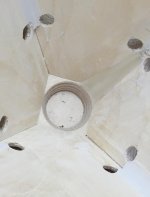
I just took a look at your photo bucket from your original thread. You did an awesome job but those frustrums are huge and trap a lot of air. GM gave good advice earlier about thinning down. The thinner the horn wall where the mids are ported, the smaller the port needs to be. But you really need to limit the amount of air trapped or what you gain with the frustrum is lost due to the low pass filtering effect.
I would hate to tear up those beautiful horns when you can probably make them sound just fine as is with the 1 Khz XO. But if you are so ambitious (or should I say obsessive") ?) you could manually mill down the hornwalls to 1/2" or so thickness where the mids attach and then re-attach the mids over the same holes. That might be "all" that it takes. But that "all" might be pretty big unless you can figure a way to guide a router precisely.
?) you could manually mill down the hornwalls to 1/2" or so thickness where the mids attach and then re-attach the mids over the same holes. That might be "all" that it takes. But that "all" might be pretty big unless you can figure a way to guide a router precisely.
I use CNC also and I'm curious how you did the tool pathing for that curve in the throat, or was that 3D printing?
I would hate to tear up those beautiful horns when you can probably make them sound just fine as is with the 1 Khz XO. But if you are so ambitious (or should I say obsessive
?) you could manually mill down the hornwalls to 1/2" or so thickness where the mids attach and then re-attach the mids over the same holes. That might be "all" that it takes. But that "all" might be pretty big unless you can figure a way to guide a router precisely.I use CNC also and I'm curious how you did the tool pathing for that curve in the throat, or was that 3D printing?
Just realized that milling down the horn wall thickness will also shrink the outer horn wall so at some point the mids will interfere with each other when mounted over the original holes and what remains of the frustrums- but only if you continue to use all 4 of them, which probably isn't necessary for home use.
To keep the same horn wall thickness, I would try filling in the frustrums. Plumber's putty works well temporarily and can be removed easily. Just keep filling in more until you've gained the couple of hundred Hz you are looking for. Replace with bondo when satisfied.
To keep the same horn wall thickness, I would try filling in the frustrums. Plumber's putty works well temporarily and can be removed easily. Just keep filling in more until you've gained the couple of hundred Hz you are looking for. Replace with bondo when satisfied.
Cool, this should be fairly easy then! You're using the same compression drive and midrange drivers that Danley is.
So the 'trick' is getting the geometry of the midrange taps correct and the crossover.
Here are the location of the taps in the Danley speaker:
Midrange taps are 3/4" in diam, 3.5" from throat
Woofer taps are 2.5" in diam, 10.5" from throat
Woofer ports are 2.5" in diam, 14.5" from throat
Where are yours? And how deep are they?
So my mid ports are 8,8 mm (0,35 inch)
The distance from the compression driver (from the bug screen to the +- middle of the entry port) 60mm (2,36 inches)
I used 18 mm birch plywood but the port depth is 3 mm
So actually I do not need a delay on the cd?
Last edited:
I use CNC also and I'm curious how you did the tool pathing for that curve in the throat, or was that 3D printing?
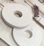
That was a combination of cnc milling a seperate disc that went from the cd angle to the angle of the horn.
I 3d printed 4 of these 'objects' per horn and glued them in, but used so much filler afterwards I probably could have done it without the 3d prints.
Attachments
That's pretty close. My measurement of the SH50 is using a ruler from the throat of the horn to the taps. It doesn't include the distance from the throat to the diaphragm.
And do you know the crossover point and slope of the sh50?
So I just found one of my first measurements of the mids. So they play a lot higher than I thought.
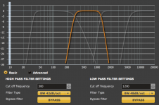
As for crossover I'm at 1200 hz now (see attachments)
Maybe I don't even need to use a crossover for the mids? or maybe at 1500hz to keep that big spike at 5k low
As for crossover I'm at 1200 hz now (see attachments)
Maybe I don't even need to use a crossover for the mids? or maybe at 1500hz to keep that big spike at 5k low
Attachments
Last edited:
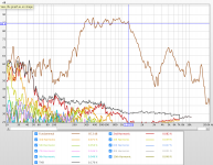
So I just found one of my first measurements of the mids. So they play a lot higher than I thought.
As for crossover I'm at 1200 hz now (see attachments)
Maybe I don't even need to use a crossover for the mids? or maybe at 1500hz to keep that big spike at 5k low
You do need some low pass attenuation for that 5 Khz peak. Also you need to get a complementary match on the slopes of the mid and CD. The slope I see on the mid is pretty steep. XOing at 1200 allows a more gradual slope on the mids which will be easier to match with the CD.
As to delay on the CD, there is really only one way to tell: do REW impulse response measurements with loopback timing reference and with your XO filters in place, separately with each driver. Delay should be added to get the starts of the rises of the IRs to align. The CD will rise more quickly than the mid because it has higher BW; alignment is when both start to rise at the same time.
And do you know the crossover point and slope of the sh50?
I don't think Danley has revealed that publicly. If he has, someone correct me.
Part of the SH50 secret sauce is the crossover.
You can still make a perfectly good coentrant horn without knowing the secrets of the SH50s crossover. The "catch" is that you'll probably need DSP to do it.
The rolloff above the midrange band is generally a very good thing (provided it goes high enough to reach the tweeter) -- that filtering is acoustic and happens AFTER the driver's contribution to distortions, and directly reduces such junk. A rolloff done in crossover before the driver, doesn't help with that a bit. I suspect this is one of the reasons for a Synergy horn's particularly nice midrange sound. (But don't judge this sound without the tweeter also playing, this is Synergy, not just a bunch of drivers playing separately).
Actually there are other (I'd say better) ways. You can use any measurement system that also measures phase response. Make combined measurements (such as Tweeter plus midranges playing all together), as well as individual measurements, then adjust their relative delays in simulator to make the summed result the same as you measured.... simple. Don't do it with crossovers in place, as you may need to adjust the crossovers in light of the resulting delays. Get the model with correct delays, then add crossovers. You can predict pretty much exactly what the result would be for each design. (I use XSim for the simulator, of course, but PCD or LSPCad would work too).
If you are going with active crossovers, then your mileage may vary (if active, I'd just adjust crossovers and delays "live" as that's not a lot different to operate than using a simulator).
As to delay on the CD, there is really only one way to tell: do REW impulse response measurements with loopback timing reference and with your XO filters in place, separately with each driver.
Actually there are other (I'd say better) ways. You can use any measurement system that also measures phase response. Make combined measurements (such as Tweeter plus midranges playing all together), as well as individual measurements, then adjust their relative delays in simulator to make the summed result the same as you measured.... simple. Don't do it with crossovers in place, as you may need to adjust the crossovers in light of the resulting delays. Get the model with correct delays, then add crossovers. You can predict pretty much exactly what the result would be for each design. (I use XSim for the simulator, of course, but PCD or LSPCad would work too).
If you are going with active crossovers, then your mileage may vary (if active, I'd just adjust crossovers and delays "live" as that's not a lot different to operate than using a simulator).
well I stand by my original statement that the only way to know is by doing measurements but I'll clarify that the IR method is simply my favorite.
I originally learned the method Bill described but had difficulty using it with my Synergy corner horns. I think the issue was my measurements had too much room in them still, despite whatever gating I was using. Which is best or easiest? I'm not going to say. IRs are interesting and useful in their own right and the discipline of EQing each driver to hit its target, e.g. LRx, curve is a good one that reduces the amount of fine tuning (hacking?) needed later in the process. When you do this first and then set the delay everything usually just falls into place.
Regardless, differential delay through the crossover filters must be taken into account. This is likely to be significant in a Synergy when you are trying to match the steep rolloff of the bandpass mids with the more gentle roll off of the CD, especially when the CD is a BMS4550 crossed at 1200 Hz, well above where its response turns down. Danley's goal was to get the bandpass chamber, mid port dimensions and locations just right so that the higher delay through the CD's high pass filter was all the delay that was needed, making a passive crossover easier.
Ultimately you will be sitting there with the measurement mic and the miniDSP control panel fine tuning the delay one click at a time, along with the PEQs. Finally, look at the step response to evaluate the time alignment of the completed crossover.
My plan is to re-measure everything again with proper documentation and trying to get things better.
For now I have a less steep high pass filter for the mids which actually sounds a little less harsch. Although with some male voices it sounds like the mids are too present, but in when measuring there equal to the highs
For now I have a less steep high pass filter for the mids which actually sounds a little less harsch. Although with some male voices it sounds like the mids are too present, but in when measuring there equal to the highs
higher delay through the CD's high pass filter
Do you mean lower delay? A high pass filter has much less passband delay than the same slope low pass filter (highpass stopband delay =lowpass passband delay). Danley was concerned about the delay to the midrange(s) resulting from its lowpass filter (both crossover and acoustic), and saw having the midranges out closer to the horn mouth as an advantageous situation for that. When I was working on passive linear phase synergy/unity horns, the problem was always not enough delay to the compression tweeter, relative to the midranges. I even had to put a messy all-pass filter into the mix to get it reasonably close.
I meant higher delay; I may have been wrong but that is what I meant
I'm a little bit surprised to hear that same slope, same cutoff frequency high pass and low pass filters don't have the same delay. I had thought they would be the same based on duality. But my tools make me work really hard to find out the group delay of individual filters so I never noticed that fact. That changes my misunderstanding of how TD does passive XOs for Synergy horns.
I do remember your CoSyn thread. Didn't Tom give you a passive XO circuit that yielded linear phase without an all pass filter and without telling you how he designed it other than saying they had designed some software to do the job? Perhaps there was some hand waving about asymmetrical filter slopes and staggered cutoff frequencies? I've played around with that on paper a bit but never gotten anywhere; DSP delay is so much easier!
My experience with needing delay in the CD path matches yours. I have equal slope electrical filters for both mid and CD. In my previous post I was speculating that asymmetrical slopes might have eliminated the need for delay. That would have required retuning the mid chamber to make it roll off faster. I was thinking higher slope electrical filter on CD but it sounds like lower slope on mids would be more effective. Moving the mids further down the horn wasn't an option for me.
- Status
- This old topic is closed. If you want to reopen this topic, contact a moderator using the "Report Post" button.
- Home
- Loudspeakers
- Multi-Way
- Unity horn bandpass sound