AllenB how would I know if that is happening?
Are you not working from measurements?
Eclipse/W6520R interesting, what size box are you using?
The PE .75cuft/20L MTM cabs.
augerpro, they measure well as is, and only making small changes to the tweeter resistor and the fill for now. But will get back around to re-measuring them someday.
wushuliu, I have a exchange program going on with the 8 x 20 baffles.
FYI, very easy to make unfinished banks with two slabs of 1/2" mdf, glue and weights.
FYI II just called PE about the missing RS28F-4, it will be re-made by a different manufacture -- very soon.
wushuliu, I have a exchange program going on with the 8 x 20 baffles.
FYI, very easy to make unfinished banks with two slabs of 1/2" mdf, glue and weights.
FYI II just called PE about the missing RS28F-4, it will be re-made by a different manufacture -- very soon.
Just thinking what difference there could actually be between the two. Lobing - between the woofers at their top end, and between the two ways around the crossover.AllenB how would I know if that is happening?
The result could be the direct level at the crossover, and the reflected contribution (level and spectrum). I thought I'd ask on what you based the two different crossovers.
Allen,
Thank you, I believe that is the word I was looking for.
The xo's were modeled, attached:
The heaver coils are on the way, should be here the end of the week, and will dive back into that this weekend.
FYI
Madisound now ships free for orders over $100!!
All these changes......
Thank you, I believe that is the word I was looking for.
The xo's were modeled, attached:
The heaver coils are on the way, should be here the end of the week, and will dive back into that this weekend.
FYI
Madisound now ships free for orders over $100!!
All these changes......
Just thinking what difference there could actually be between the two. Lobing - between the woofers at their top end, and between the two ways around the crossover.
The result could be the direct level at the crossover, and the reflected contribution (level and spectrum). I thought I'd ask on what you based the two different crossovers.
Attachments
It looks as though you have modelled that crossover on making a perfect null on axis with reversed polarity. Now, I'm only guessing here but when I design a crossover it doesn't always do that because all directions are being considered (for TM or MTM). Another example, IIRC D'Appolito explored 90 degrees phase difference to splay the two inverted sets of lobes to fill the gaps.
What I would be interested in here, is vertical polars. Woofers on their own, and all drivers combined. I'd also wonder if there is any difference between the two speaker types if their response was the same and there were ceiling absorbers. -Just thinking aloud, please carry on.
What I would be interested in here, is vertical polars. Woofers on their own, and all drivers combined. I'd also wonder if there is any difference between the two speaker types if their response was the same and there were ceiling absorbers. -Just thinking aloud, please carry on.
Hey ODougbo.
What's the xo frequency and the M-to-M center-to-center separation? I'm considering MTM with a very large tweeter and models predict lobing to be an issue. Would appreciate your input as to how much you can perceive lobing effects in your build. Maybe your design adheres by established rules and hence not perceivable - hence I was asking for distance and xo frequency.
Cheers!
Allen, I thought a perfect null was the always the goal.
No ceiling damping, but was just thinking this room with a 9' ceiling is way better the the old house (we moved).
Again, crazy bass from the TMM, we watched KONG 2017 and sounded like my 50lb CSS 12" woofer was hooked up, but no, it is in storage. Even more inexpressive tho, is all this crazy sound from a 100 watt HT receiver, turned up about 1/3 of the way.
FYI The receiver is connected to the STB via Toslink, set to stereo.
Lewinski, sounds like you are starting from scratch, my best advice would be build some test boxes and start experimenting.
No ceiling damping, but was just thinking this room with a 9' ceiling is way better the the old house (we moved).
Again, crazy bass from the TMM, we watched KONG 2017 and sounded like my 50lb CSS 12" woofer was hooked up, but no, it is in storage. Even more inexpressive tho, is all this crazy sound from a 100 watt HT receiver, turned up about 1/3 of the way.
FYI The receiver is connected to the STB via Toslink, set to stereo.
It looks as though you have modelled that crossover on making a perfect null on axis with reversed polarity. Now, I'm only guessing here but when I design a crossover it doesn't always do that because all directions are being considered (for TM or MTM). Another example, IIRC D'Appolito explored 90 degrees phase difference to splay the two inverted sets of lobes to fill the gaps.
What I would be interested in here, is vertical polars. Woofers on their own, and all drivers combined. I'd also wonder if there is any difference between the two speaker types if their response was the same and there were ceiling absorbers. -Just thinking aloud, please carry on.
Lewinski, sounds like you are starting from scratch, my best advice would be build some test boxes and start experimenting.
If you consider the overall sound power, also the nature of the reflections, you can adjust the direct ratio by being off on the phase if it works out that way. Preferably up away from the floor as wellAllen, I thought a perfect null was the always the goal.
")
If I use a standard first order filter as an example, response is -3dB for both drivers and phase is 90 degrees apart. On axis the response adds up to 0dB but on one side of the lobe it rises to +3dB and on the other side it falls toward a null. If you were to bring the phase together on axis, all that changes is the physical angle of the lobe, and the on axis response.
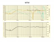
Took longer than expected, but new xo's are finished. There are a few small changes to the mtm xo design, which I would recommend. They needed just a little more top end, so bypassed the 2.7 series resistor, which sounds very nice, balanced and mellow. Dialogue is better than ever. These mtm's do have a better sound stage; sounds from far left/right. As mentioned the sound is very relaxed and easy listening.
Downside? Maybe gave up a little bass compared to the TMM, not much tho.
I keep a Richard Elliott program on the DVR, amazing really on the TMM. Folks that come over are mesmerized by the sound.
Curious about RS28 replacement.
Downside? Maybe gave up a little bass compared to the TMM, not much tho.
I keep a Richard Elliott program on the DVR, amazing really on the TMM. Folks that come over are mesmerized by the sound.
Curious about RS28 replacement.
Attachments

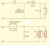
The network configuration is more geared to an MTM rather than a TMM. One does not parallel the woofers in a TMM. The concept of a TMM is to roll off the lower driver early 200-500 Hz to avoid interference at crossover because the drivers are not equidistant from the tweeter. The classic TMM design has higher gain at low frequencies from the combined output and relieves the network from baffle step compensation. The series inductor can then be smaller on the upper woofer. Look at the network configuration for a TMM in Troels Gravesen's website for the Nomex 164. This is not an optimum TMM.
I have a friend that dislikes mtm setups.
He says it sounds like you are listening to music looking down a pipe.
A low crossed tweet mtm, that I'd like to hear.
But 2 x 5" frame plus 1" tweet would need 1200hz to look like a point source (vertically).
Tmm doesn't have to be baffle step only.
I crossed my double 15's at 750hz, sounded awesome at 11'.
But you bring up a good point.
Klipsch oldest rf7 crossed dual 10's at 2,200hz both in parallel.
When i had a different double 15 setup 80-750hz i ran each 15 in its own box, stacked one on the baffle step inductored one. At low volume adding the baffle step woofer made no difference, it made a little difference at medium volumes, and a big difference at high volume.
Still don't know the takeaway on that one.
Using the exact same crossover, mtm vs tmm, i think what you (difference) hear at your chair is the reflection of the vertical freq response bounce off the ceiling / floor.
Check out dunlavy sc1 3.5khz crossed 1" dome with a big faceplate to 5.5"ers (mtm).
You see a dip in vertical dispersion at maybe 700hz.
Dunlavy Audio Labs SC-I loudspeaker Measurements | Stereophile.com
Another successful mtm not baffle stepped for mixing is the lipinski L707.
Dual 7" fiberglass plus vifa ring radiator (xt 19?), stated 2khz crossover, mentioned stay within 5 degrees +/- vertically.
Lipinski Sound L-707 loudspeaker | Stereophile.com
Last edited:
Generally, common box speaker should be optimized for both axial and power responses. With that policy, MTM is probably more suitable if tweeter is mini-dome, diameter max. 70 mm. But if tweeter is normal or big size with diameter of 97...130 mm, TMM is probably more balanced compromise.
M-M distance of TMM is worth to optimize. 50..70 mm extra gap between mid-woofers is expected to get the smoothest axial, power and DI.
MTM and TMM have slightly different crossover because axial/power optimization produces a bit different compromise due to shape of DI response.
MTM could benefit from phase mismatching at the crossover frequency to get smoother power & DI.
Where did you get this information. I am currently trying to find the optimum distance between Ms for a TMMM configuration..
M-M distance of TMM is worth to optimize. 50..70 mm extra gap between mid-woofers is expected to get the smoothest axial, power and DI.
I am also curious what the impact is from having a wider gap between the top 2 Ms and the bottom 2. If I let the enclosure braces dictate, the gap between M1 and M2 is 80 mm while the gap between M2 and M3 can be 50 mm.
Where did you get this information.
This can be studied and optimized with a simulator. I've used quite simple MT speaker with full polar response measurement set. Double M in the simulation, move 2nd M down and optimize crossover by axial and power responses. Iterate few times until DI response is smooth up to crossover frequency. Verify that vertical directivity is okay (not excessive beaming).
Basic theory: Directivity index is smoother when vertical directivity of M-M pair 'succesfully' extends directivity of individual cones to lower frequencies. In addition, if M-M distance is longer than T-M distance, peaks in vertical directivity spread to wider range close to crossover frequency.
About TMMM: Multiple mid-woofers reduce power due to higher directivity which could be compensated with higher axial pressure at midrange or horn tweeter.
The result depends on a lot of things.. however,
In general:
The pressure gradient changes at higher freq.s for the mid-bass line. This is a condition of vertical axis measurement angle (usually from the tweeter) in relation to cancellation from using more than one driver in the midrange/midbass line.
Specifically:
The closer you get to the baffle, the more high freq. loss (from cancellation) you'll get from the MMT line vs. a MTM line when
- measuring from the tweeter's position. (..which is standard.)
Smaller diameter midrange/midbass drivers improve this situation.
Tighter spacing between midranges/midbass drivers improve this situation.
Tighter spacing between the tweeter and the midrange/midbass line improves this situation.
Enhanced pressure from diffraction (at higher freq.s) can improve this situation (and can vary with placement on baffle for the midgrange/midbass line).
..and of course, your crossover region and particularly SLOPE is critical (..the lower your freq. and the steeper the slope in the aggregate for the design - the better the result).
A good (objective) TMM is harder to design than a good MTM.
Almost no one designs either (TMM or MTM) in relation to the pressure gradient (instead with a static distance from the baffle - often more than a meter), and most only design with respect to a *VERY* narrow vertical range. (..meaning most designs using either method are often flawed - and typically very flawed.)
Ex. "woo-hoo! -got a good response from 2 meters plus distance on tweeter axis and a 30 degree vertical "window". Most listeners are going to sit within this window so everything is A-OK."
It's not.
I have a friend that dislikes mtm setups.
He says it sounds like you are listening to music looking down a pipe.
This might be due to that MTM has inherent directivity problems. Off axis always have none linear behaviour in MTM.
//
- Status
- This old topic is closed. If you want to reopen this topic, contact a moderator using the "Report Post" button.
- Home
- Loudspeakers
- Multi-Way
- MTM - TMM Shoot Out