From what I can see...
That is more or less my intuition too.
However Earl claims that a hyperbolic horn (AKA OS waveguide) can actually "pull" open the directivity.
I don't see this in the maths but, to be honest that maths is near my limit.*
So I hesitate to contradict an expert like Earl, but even experts make mistakes.
We shall see after I study a bit more over Xmas, ABEC is the next step unless I find a better software option.
* Actually, it's near to the limit of what can be solved with closed form equations.
** Thread is >HERE< if you're interested.
Best wishes
David
Last edited:
OK, I managed to solve this one (literally.)
If anyone else is losing their minds with ABEC, here's some stuff that helped me:
1) I wound up drawing my waveguide on a piece of graph paper. I gave up on making it in 123D and importing a mesh. I basically made something on graph paper that looks like an Akabak waveguide, but this time in three dimensions, not one.
Why not use ABEC shells for a preliminary design concept? Everything is native ABEC. I found this helpful in trying to drive.
2) My big 'Eureka' moment was when I looked at the performance of my laptop: ABEC was using up all my memory then hitting a wall. So that's why my sims were 'stuck' at 32%. The program isn't smart enough to know that it's run out of RAM.
This sounds strange. If you needed more RAM the OS would page swap using your HD so everything just slows down. My desktop used to have 8GB and I ran all the demo models and my own Omni model with 2K elements without issues. I upgraded to 16GB RAM and it made no difference.
3) To fix the RAM issue, I dropped my maximum frequency from 15khz to 5khz, and then I inched it up until it stopped working. (I think I settled at 7khz.) My laptop only has 8gb of RAM, so you should be fine if you have 16-32gb of ram. As I understand it, ABEC uses the maximum frequency to determine the size of the mesh. IE, if you have a maximum frequency of 10khz you're going to need way way more RAM than if the max was 5khz.
<snip.
I think this is the real issue. If you specify (or need) higher mesh frequency (smaller mesh) its brutal on solve time. In one of my models a 2K element mesh freq takes 10min to solve @2K mesh freq. If I increase from 2K to 5K the time goes up to 1 hr. If I want 15K it will take 4hrs. ABEC only appears to die (stall) for long periods and it still may iterate or time out in the end for model problems.
One factor here - which won't affect most people:
I have a HP Ryzen laptop. For some unknown reason, it comes with a conventional hard drive. When I replaced the hard disk with a SSD, I had to tweak a bunch of Windows settings so that I could duplicate the drive with Parted Magic. It took the better part of a day to clone the disk. Among these, I turned off the swap file. I re-enabled it, but Windows might be having issues since it's a cloned disk.
I have a HP Ryzen laptop. For some unknown reason, it comes with a conventional hard drive. When I replaced the hard disk with a SSD, I had to tweak a bunch of Windows settings so that I could duplicate the drive with Parted Magic. It took the better part of a day to clone the disk. Among these, I turned off the swap file. I re-enabled it, but Windows might be having issues since it's a cloned disk.
I haven't run into any limitations using the demo. Because the model of the loudspeaker is determined by the inputs in the text files, you can model anything as long as you save your files with notepad. The only downside that I can see is that you have to re-run your sims. But even Robin Christ's waveguide demo, with thousands of verticies, can be simmed on my quad core laptop in about 10-15 minutes.
I actually filled in the "non commercial" free license request and never got a response. I still use the demo, its just a pain when the mesh frequency gets high and I can't save a 4hr sim.
ABEC does recognize when a file has changed when you create the project and register (include) your files. If you use NotePad++ there is a language overlay that formats the text files (keywords, etc) making them easier to read.
Last edited:
Definitely.
What would *really* make it scream is if they created a version that supports GPU.
For instance, it takes about sixteen hours to convert a H264 video clip into h265 on my six core AMD running at 3.0ghz. The same task on a $99 GPU like the Nvidia 1050 takes about 15 minutes!
The Nvidia 1050 has 640 CUDA cores, and it just SCREAMS at highly parallel tasks, like video encoding or 3D rendering.
EDIT: Comsol doesn't support GPUs, so I may be wrong about the suitability of CUDA for BEM : CUDA and COMSOL
Last edited:
exactly ") GPU would be great, anyway I tried up to 56 threads on ABEC working great. (2x E5-2697)
GPU would be great, anyway I tried up to 56 threads on ABEC working great. (2x E5-2697)
GPU would be great, anyway I tried up to 56 threads on ABEC working great. (2x E5-2697)Definitely.
What would *really* make it scream is if they created a version that supports GPU.
For instance, it takes about sixteen hours to convert a H264 video clip into h265 on my six core AMD running at 3.0ghz. The same task on a $99 GPU like the Nvidia 1050 takes about 15 minutes!
The Nvidia 1050 has 640 CUDA cores, and it just SCREAMS at highly parallel tasks, like video encoding or 3D rendering.
EDIT: Comsol doesn't support GPUs, so I may be wrong about the suitability of CUDA for BEM : CUDA and COMSOL
...around the Intel 9900k...
ABEC looks like the push I needed to update my computer.
What do people here run it on, CPU(s), speed, RAM, disk etc?
Any recommendations, either technical or best buy?
Does ABEC avoid any of the numerical artifacts that Axidriver sometimes showed?
David
Keep in mind; abec always uses 1 thread per frequency, so always use a multiple of freqs of the number of threads you jave available.
For instance, i have ordered a i9-9960 which has 16 cores/32 threads, so i can simulate 32 freqs in one run, if i want more freqs, i should do 64 because else i am just throwing away time.
Ps, this processor with liquid cooling and 64gb ram makes for a nice abec machine
For instance, i have ordered a i9-9960 which has 16 cores/32 threads, so i can simulate 32 freqs in one run, if i want more freqs, i should do 64 because else i am just throwing away time.
Ps, this processor with liquid cooling and 64gb ram makes for a nice abec machine
I just built a rig around the Intel 9900k so I want to take advantage of that power.
That's a beast!
Here's some more tips:
I am finding that I must change how I do my 3D models. For instance, when I build waveguides, I generally use circles and lines.
Like this:


From here: 3D Modeling Tips and Tricks
I am finding that this method doesn't work so hot with ABEC. Here's why:
We make the model in something like Fusion or Sketchup or 123D. And then we convert that model to a solid in FreeCad. The problem is that you wind up with way, WAY too many faces. You can reduce the number of faces in meshlab, but easily 80% of the time I wind up with a broken model, even with a modest reduction in the face count.
I tried about a million different solutions, but the one that seems to work is to just use polygons instead of circles. For instance, if I use a sixteen sided polygon as the basis for my waveguides, the number of polygons in the final solid is way lower.
I am finding that I must change how I do my 3D models. For instance, when I build waveguides, I generally use circles and lines.
Like this:
From here: 3D Modeling Tips and Tricks
I am finding that this method doesn't work so hot with ABEC. Here's why:
We make the model in something like Fusion or Sketchup or 123D. And then we convert that model to a solid in FreeCad. The problem is that you wind up with way, WAY too many faces. You can reduce the number of faces in meshlab, but easily 80% of the time I wind up with a broken model, even with a modest reduction in the face count.
I tried about a million different solutions, but the one that seems to work is to just use polygons instead of circles. For instance, if I use a sixteen sided polygon as the basis for my waveguides, the number of polygons in the final solid is way lower.
Hi Patrick,
I'm not familiar with Sketchup, but why would you convert a Fusion model to FreeCad? From Fusion you can export a model as STEP-file (*:stp), which can be opened in GMSH.
I'll come back to this as part of the step-by-step description...
We make the model in something like Fusion or Sketchup or 123D. And then we convert that model to a solid in FreeCad.
I'm not familiar with Sketchup, but why would you convert a Fusion model to FreeCad? From Fusion you can export a model as STEP-file (*:stp), which can be opened in GMSH.
This is something I experienced with FreeCad as well, but not with Fusion.The problem is that you wind up with way, WAY too many faces.
Same with me, when starting over with too many faces for meshing (I usually use GMSH).You can reduce the number of faces in meshlab, but easily 80% of the time I wind up with a broken model, even with a modest reduction in the face count.
This issue was the reason for me to switch from FreeCad to Fusion and simply export *stp from there. No issues with circles or elliptical surfaces resulting in too many surfaces so far.I tried about a million different solutions, but the one that seems to work is to just use polygons instead of circles. For instance, if I use a sixteen sided polygon as the basis for my waveguides, the number of polygons in the final solid is way lower.
I'll come back to this as part of the step-by-step description...
Success! I finally managed to get an ABEC sim to work, using a model that I designed myself, with a CAD program.
This is a first. A few years back I managed to get ABEC to work using a modified version of the included sims (1) and earlier this month I managed to get ABEC working using a model that I designed on graph paper(2).
But this is the first time it's worked with a 3D model, made in CAD.
So, in case anyone else has struggled with ABEC, here's what worked for me:
1) I've found that Autodesk's "MeshMixer" is a million times better at reducing the polygon count of a model. I don't think I could've achieved usable results with Meshlab, I was constantly seeing issues where the model would have holes in it.
2) If ABEC gets 'stuck', consider reducing the upper limit of your sim. I have a quad core Ryzen and 8gigs of ram, I wasn't able to do sims above 5khz. Symmetry can allow you to increase that further, but I'm not using symmetry.
3) This one was huge, and I imagine that 99% of the people reading this won't run into this. But in case you do... I am making models in 123D, then I'm transmogrifying them in Meshmixer, then turning them into a solid in FreeCAD, then turning them into a mesh in GMSH. As described here. Here's the problem: when you import that mesh into ABEC, there's absolutely zero scale information. IE, ABEC has no idea if your model is ten inches in diameter or ten miles in diameter. This problem was KILLING me, for days. I found that I could import a mesh into ABEC, I could manipulate a mesh, but I couldn't SOLVE anything. The issue was the lack of scale. ABEC would happily let me examine my model, because the coordinates were perfectly valid, but with no information to describe the scale of the model, simulation was absolutely impossible. I went in circles with this one for DAYS, because I thought the issue was that my model wasn't airtight, or that I was using a demo version of ABEC, or that there was a syntax error in one of my scripts. But it wasn't any of that. The problem was that I was missing one line in my "solving.txt" script, which would describe the scale of my mesh. It should look like this:
MeshFile_Properties
MeshFileAlias=M
Scale=1mm
Note that the NAME and the SCALE of your mesh will depend on what you made in your 3D program. For instance, my 3D program (123D) uses millimeters by default. So I need to set this parameter in ABEC, because the scale of the model gets nuked during the transmogrification from 123d to STL to STP to MSH. YMMV and a lot will depend on how you're getting your model from CAD and into ABEC.
4) I don't have a great grasp on the concept of "driving" and "diaphragm", but I found that I was able to get "driving" to work and I couldn't get "diaphragm" to work.
Here's an animation of one of my ABEC sims. This is an elliptical oblate spheroidal waveguide. Not that the bandwidth is fairly limited, because I need more RAM. It taps out at 5000Hz. I'll get that up to 15,000Hz with some work.
(1) Car Audio | DiyMobileAudio.com | Car Stereo Forum - View Single Post - Horn Loading a Full Range / It'll End In Tears
(2) ABEC experts - help!
Hi,
Thanks as well for sharing your solution!
Here and here are descriptions on how to convert a *.stl file to a *.stp file for import in GMSH.
However, note that *.stl files are already 'meshes' and not the best format for simulations with ABEC. With the conversion to *.stp you have to calculate back to a solid form. Better approach would be to start over with a *.stp file directly from the 3D-model for simulations and derive the *stl file later for printing.
I assume 123D can't do this and just exports *stl (?). However, other 3D-CAD software like FreeCAD or Fusion 360 can. This will ease up ABEC simulations quite a bit.
This procedure is as well suggested by the ABEC help:
Thanks as well for sharing your solution!
I am making models in 123D, then I'm transmogrifying them in Meshmixer, then turning them into a solid in FreeCAD, then turning them into a mesh in GMSH.
Here and here are descriptions on how to convert a *.stl file to a *.stp file for import in GMSH.
However, note that *.stl files are already 'meshes' and not the best format for simulations with ABEC. With the conversion to *.stp you have to calculate back to a solid form. Better approach would be to start over with a *.stp file directly from the 3D-model for simulations and derive the *stl file later for printing.
I assume 123D can't do this and just exports *stl (?). However, other 3D-CAD software like FreeCAD or Fusion 360 can. This will ease up ABEC simulations quite a bit.
This procedure is as well suggested by the ABEC help:
Attachments
1. Disclaimers and the 3D-CAD model
As promised above, I try to give a step-by-step description on how I did ABEC-simulations starting with a 3D-CAD model - here one of Brandons waveguides as an example.
Some disclaimers, before I start over:
1. This is just the way I performed the simulations, not necessarily the most elegant. Please comment, if you see improvements...
2. There are quite some users around here and on other forums with much more knowledge on ABEC, simulations etc. , e.g. nailhead or JFA or... please jump in and correct me where required.
3. There are two threads in a German audio DIY forum on the topic, i.e. one thread on 'how-to' use ABEC (Der ABEC Thread...) and one thread on how-to construct constant directivity waveguides (Wir basteln ein Waveguide oder Constant Directivity, wie geht das?) with a lot of basic simulations on horns and waveguides using ABEC or AxiDriver. A lot of information there, however, you have to register to see images and may have to translate.
4. Use the ABEC help and examples! Almost all things asked and discussed here, can be found in the very good ABEC help file.
5. I show steps which most of you probably already know, just to be clear for beginners.
5. Have fun.
Step 1 - the CAD model
Starting from one of Brandons WGs, I converted the *.stl file to a *.stp file - please check Patricks description how to do this.
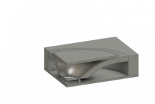
I then built my own 3D-model around the respective WG contour. Some hints and images to illustrate.
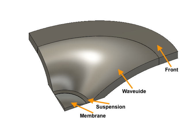
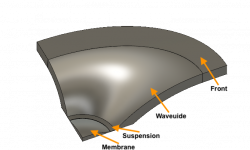
To get to this point,
- you have to build a body from the WG contour,
- you need at least a membrane and the waveguide,
- I added a suspension (depends on if you like to include the tweeter membrane and suspension to the simulation later) and a WG-surface (depends if you just want to simulate in an infinite baffle or in an enclosure later).
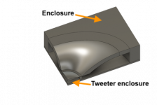
I then added...
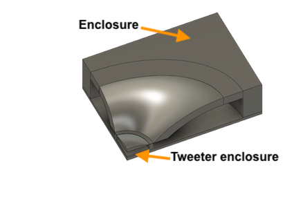
...an enclosure. Or rather two enclosures, a back-enclosure for the tweeter and an enclosure for the entire WG. May be needed later, depending on what you intend to simulate.
Finally...
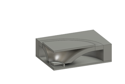
...I added an interface in front or the WG mouth. The interface sits between the inside of the WG and the 'outside'. This helps with the ABEC simulation later.
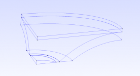
I already showed a quarter model her. Actually, the 3D-model was built up as a full 360° model first and the finally divided into quarters.
It's extremely helpful to do this in order to achieve reasonable calculation times in ABEC later. ABEC can use symmetries - use symmetries wherever possible...
Check, if your model has been set up in the 3D-CAD programm using inch or mm or cm - you have to know this when it comes to ABEC later.
How to go on with this? If you have your 3D-model, it has to be exported as *.stp file.
Next post will show how the stp-file shown above looks like after import to GMSH and how meshing is done.
Christoph
As promised above, I try to give a step-by-step description on how I did ABEC-simulations starting with a 3D-CAD model - here one of Brandons waveguides as an example.
Some disclaimers, before I start over:
1. This is just the way I performed the simulations, not necessarily the most elegant. Please comment, if you see improvements...
2. There are quite some users around here and on other forums with much more knowledge on ABEC, simulations etc. , e.g. nailhead or JFA or... please jump in and correct me where required.
3. There are two threads in a German audio DIY forum on the topic, i.e. one thread on 'how-to' use ABEC (Der ABEC Thread...) and one thread on how-to construct constant directivity waveguides (Wir basteln ein Waveguide oder Constant Directivity, wie geht das?) with a lot of basic simulations on horns and waveguides using ABEC or AxiDriver. A lot of information there, however, you have to register to see images and may have to translate.
4. Use the ABEC help and examples! Almost all things asked and discussed here, can be found in the very good ABEC help file.
5. I show steps which most of you probably already know, just to be clear for beginners.
5. Have fun.
Step 1 - the CAD model
Starting from one of Brandons WGs, I converted the *.stl file to a *.stp file - please check Patricks description how to do this.
I then built my own 3D-model around the respective WG contour. Some hints and images to illustrate.
To get to this point,
- you have to build a body from the WG contour,
- you need at least a membrane and the waveguide,
- I added a suspension (depends on if you like to include the tweeter membrane and suspension to the simulation later) and a WG-surface (depends if you just want to simulate in an infinite baffle or in an enclosure later).
I then added...
...an enclosure. Or rather two enclosures, a back-enclosure for the tweeter and an enclosure for the entire WG. May be needed later, depending on what you intend to simulate.
Finally...
...I added an interface in front or the WG mouth. The interface sits between the inside of the WG and the 'outside'. This helps with the ABEC simulation later.
I already showed a quarter model her. Actually, the 3D-model was built up as a full 360° model first and the finally divided into quarters.
It's extremely helpful to do this in order to achieve reasonable calculation times in ABEC later. ABEC can use symmetries - use symmetries wherever possible...
Check, if your model has been set up in the 3D-CAD programm using inch or mm or cm - you have to know this when it comes to ABEC later.
How to go on with this? If you have your 3D-model, it has to be exported as *.stp file.
Next post will show how the stp-file shown above looks like after import to GMSH and how meshing is done.
Christoph
Attachments
2. GMSH: *stp file import and meshing
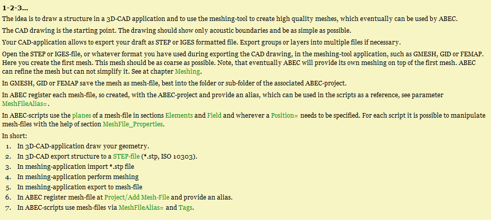
Next step is to import the *.stp-file (exported from the CAD-programm) into GMSH.
To keep it simple, here the minimal *.stp-file consiting only of membrane, suspension (or tweeter front), waveguide and interface.
In GMSH the stp-file looks like this after import:
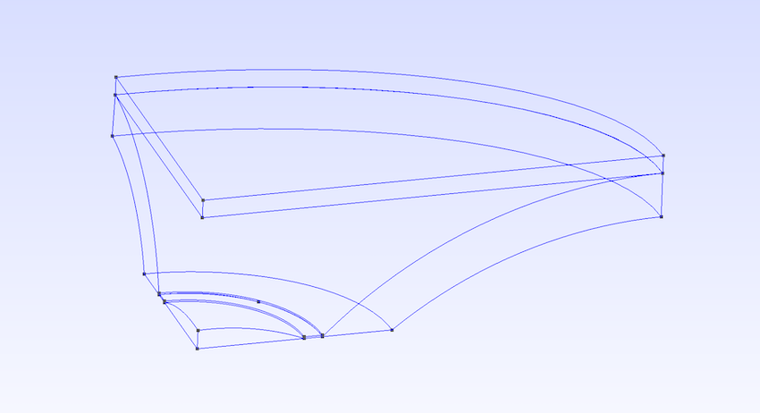
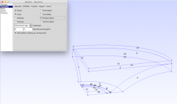
Addition of surface labels shows the total number of surfaces and their assignment to the respective surface.

Please refer to post #18 to see how this is done. You'll need these numbers for the ABEC script later to choose the right surfaces needed for your simulation.
After meshing, the waveguide looks like this:

Please note that the resolution of the mesh is determined by the 'Element size number'. I recommend to experiment a bit here. The finer the mesh, the higher in frequency simulations can be performed later - but the longer the calculation time will be to solve the respective file. The size of the mesh-file is a good measure, if the mesh will work fine later. Here, sizes around 100kB to 250kB worked fine for me.
Choose 'export mesh' in order to get your mesh-file for import in ABEC.
I used a mesh-file of 144kB for import into ABEC for the following simulations. Let's see, how this works out...
Any questions so far?
Next step is to import the *.stp-file (exported from the CAD-programm) into GMSH.
To keep it simple, here the minimal *.stp-file consiting only of membrane, suspension (or tweeter front), waveguide and interface.
In GMSH the stp-file looks like this after import:
Addition of surface labels shows the total number of surfaces and their assignment to the respective surface.
Please refer to post #18 to see how this is done. You'll need these numbers for the ABEC script later to choose the right surfaces needed for your simulation.
After meshing, the waveguide looks like this:
Please note that the resolution of the mesh is determined by the 'Element size number'. I recommend to experiment a bit here. The finer the mesh, the higher in frequency simulations can be performed later - but the longer the calculation time will be to solve the respective file. The size of the mesh-file is a good measure, if the mesh will work fine later. Here, sizes around 100kB to 250kB worked fine for me.
Choose 'export mesh' in order to get your mesh-file for import in ABEC.
I used a mesh-file of 144kB for import into ABEC for the following simulations. Let's see, how this works out...
Any questions so far?
Attachments
3. ABEC: Import of mesh and basic settings
OK, no questions - then last step, i.e. import to ABEC and basic settings for a simulation.
Import of mesh file:

Scripts:
- Boundary Element Script:
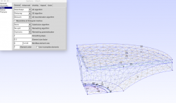
Define 'Control Solver'
Just some brief notes: f1, f2, number of frequencies and abscissa log are probably self-explanatory. Delaunay is one possible meshing algorithm (don't ask me, my math is not good enough...).
Important is symmetry 'Sym=xz'. This results in a full 360° WG.
Then mesh file properties, subdomain properties, elements and driving have to be defined. As we model in an infinite baffle, this has to be defined as well.
- Mesh file properties:
- Subdomain properties:
- Infinite baffle:
As we simulate in an infinite baffle for sake of simplicity, this has to be defined.
- Elements:
We have to define the elements of th ewaveguide, membrane and so on.
Same system for all elements. Assign the correct subdomain for the element, if you like a color, the respective mesh file you refer to, shift coud be used to shift the element in ABEC (not needed here), Rotate is used to rotate the elements, just to bring the waveguide mouth in y-axis direction (can be done as you like, however, has to be aligned with the Observation scripts). Mesh include is important, here you list the number of the surfaces as defined in GMSH. For example, the waveguide contour is surface 13 (see GMSH image).
What's missing? You have to 'drive' the membrane. One possibility is to use the 'Driving' command:
How does this look like in ABEC?

You see the membrane (red) and the waveguide inside and tweeter front (blue) and the interface (no color, as you are looking on top of it, would be yellow from the WG inside).
The 'normals' of surfaces appear to be colored, if you look at them - and transparent, if you look at their back. It is important, that 'normals' of surfaces are facing the right direction (e.g. the waveguide contour or membrane should 'look' to the inside of the waveguide). The interface has to 'look' into the waveguide - again, all this is defined and described in the help file....
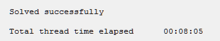
Everything ready for solving. Time for solving using this mesh/example (and take advantage of symmetry!) was...

Next post will give the Observation script and finally the simulation results in VACS.
OK, no questions - then last step, i.e. import to ABEC and basic settings for a simulation.
Import of mesh file:
Scripts:
- Boundary Element Script:
Define 'Control Solver'
Again, please refer to the ABEC help file for explanations and the 'how-to ABEC'-thread mentioned before for detailed step-by-step description how to set up ABEC.Control_Solver
f1=1000; f2=20000; NumFrequencies=50; Abscissa=log;
Meshing=Delaunay
Sym=xz
Dim=3D
MeshFrequency=500Hz
Just some brief notes: f1, f2, number of frequencies and abscissa log are probably self-explanatory. Delaunay is one possible meshing algorithm (don't ask me, my math is not good enough...).
Important is symmetry 'Sym=xz'. This results in a full 360° WG.
Then mesh file properties, subdomain properties, elements and driving have to be defined. As we model in an infinite baffle, this has to be defined as well.
- Mesh file properties:
Note that it is referred to the imported mesh file here (M1) and that a scale is given (very important - see Patricks post).MeshFile_Properties "Waveguide"
MeshFileAlias="M1"
Scale=1mm
- Subdomain properties:
Two subdomains are defined, inside (=inside Waveguide, interior) and outside (=outside Waveguide, exterior). Colors can be assigned...SubDomain_Properties 'Inside Waveguide'
SubDomain=1
ElType=Interior
Color = blue
SubDomain_Properties 'Outside'
SubDomain=2
ElType=Exterior
Color=green
- Infinite baffle:
As we simulate in an infinite baffle for sake of simplicity, this has to be defined.
The subdoain is exterior/outside (see above). Important is the position, here plane y and an offset of .75 in (=height of the waveguide, i.e. height of the WG-mouth).Infinite_Baffle
Subdomain=2
Position=y Offset=0.75in
- Elements:
We have to define the elements of th ewaveguide, membrane and so on.
Elements "Waveguide inside"
SubDomain=1
MeshFileAlias="M1"
Shift= 0mm, 0mm, 0mm
Rotate = -90.0, 0.0, 0.0
Color = blue 0.7
101 Mesh Include 13
Elements "Tweeter Front"
SubDomain=1
MeshFileAlias="M1"
Shift= 0mm, 0mm, 0mm
Rotate = -90.0, 0.0, 0.0
Color = blue 0.7
101 Mesh Include 9 SwapNormals
Elements "Interface"
SubDomain=1,2
MeshFileAlias="M1"
Shift= 0mm, 0mm, 0mm
Rotate = -90.0, 0.0, 0.0
Color = yellow 0.7
101 Mesh Include 25
Elements "HT Front"
SubDomain=1
Color=Red 1
MeshFileAlias="M1"
Shift= 0mm, 0mm, 0mm
Rotate = -90.0, 0.0, 0.0
101 Mesh Include 19
Same system for all elements. Assign the correct subdomain for the element, if you like a color, the respective mesh file you refer to, shift coud be used to shift the element in ABEC (not needed here), Rotate is used to rotate the elements, just to bring the waveguide mouth in y-axis direction (can be done as you like, however, has to be aligned with the Observation scripts). Mesh include is important, here you list the number of the surfaces as defined in GMSH. For example, the waveguide contour is surface 13 (see GMSH image).
What's missing? You have to 'drive' the membrane. One possibility is to use the 'Driving' command:
It is referred to the 'HT Front' element, i.e. the HT diaphragm. Driving direction is y, i.e. the 'direction' of the waveguide which has been defined by the 'Rotate' command.Driving
RefElements="HT Front"
DrvGroup=2001
Direction=y
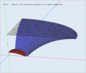
How does this look like in ABEC?
You see the membrane (red) and the waveguide inside and tweeter front (blue) and the interface (no color, as you are looking on top of it, would be yellow from the WG inside).
The 'normals' of surfaces appear to be colored, if you look at them - and transparent, if you look at their back. It is important, that 'normals' of surfaces are facing the right direction (e.g. the waveguide contour or membrane should 'look' to the inside of the waveguide). The interface has to 'look' into the waveguide - again, all this is defined and described in the help file....
Everything ready for solving. Time for solving using this mesh/example (and take advantage of symmetry!) was...
Next post will give the Observation script and finally the simulation results in VACS.
Attachments
OK, no questions...
Import of mesh file:
...
This picture does not load in my browser (Chrome), others are fine.
Very educational, thank you, one question - I see references to Gmsh and also Gmesh.
Gmsh seems popular, do you really use Gmesh too or is it a typo?
Best wishes
David
- Status
- This old topic is closed. If you want to reopen this topic, contact a moderator using the "Report Post" button.
- Home
- Loudspeakers
- Multi-Way
- ABEC experts - help!