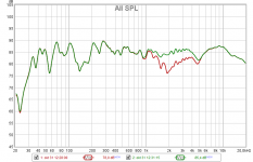
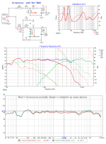
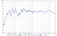
Flipped the cables at the crossover and there was a clear audible difference. Red line is after I flipped the cables. Weird that everything is now right when connecting according to the marking on the drivers

Measurement was done ~1m in front of the left speaker at their current position, so not in the middle of the room.
Attachments
Thanks Niklas,
Go with ( quite obviously ) the driver polarities that correspond to the green trace.
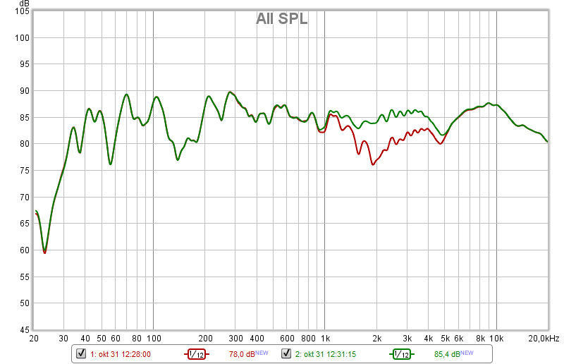
To treat the "suckout" of the frequency range between 100 and 200hz you would need to treat the walls behind the speakers ( if you desired ) with absorbers.
- That looks to be "wall bounce" and is known as SBIR.
I've previously mentioned that the symmetrical 5K notch ( is most likely a diffraction issue from the enclosure & the nearby woofers ) and would be somewhat treatable with a felt cowling around each tweeter.
- BTW, reclaiming those frequencies will give you the impression of a louder tweeter.
All-in-all, the result is as expected, with quite good low frequency extension.
Niklas said:Red line is after I flipped the cables.
Go with ( quite obviously ) the driver polarities that correspond to the green trace.
Niklas said:Weird that everything is now right when connecting according to the marking on the drivers.
To treat the "suckout" of the frequency range between 100 and 200hz you would need to treat the walls behind the speakers ( if you desired ) with absorbers.
- That looks to be "wall bounce" and is known as SBIR.
I've previously mentioned that the symmetrical 5K notch ( is most likely a diffraction issue from the enclosure & the nearby woofers ) and would be somewhat treatable with a felt cowling around each tweeter.
- BTW, reclaiming those frequencies will give you the impression of a louder tweeter.
All-in-all, the result is as expected, with quite good low frequency extension.
Last edited:
How big of an absorber would I need to treat that suckout between 100-200Hz? The front of the speaker is ~55cm from the wall and quarter wavelength gives me 155Hz which is right in the middle of that suckout.
As for the 5kHz notch, I know it's not pretty but the solution wouldn't be pretty either unless I build some sort of front grille for the speakers. The grille would also add more sharp edges around the drivers which I guess would have an impact on the sound as well.
I will do some tests with lower resistor values in the tweeter circuit next week or whenever I have time. I will also try to do some measurements to compare with the old ones.
The 100-200hz suckout looks to be ( as severe as it is ) because I think there are 3 separate cancellations arriving at the same time ( ie; not just the back wall is involved ).
The typical absorber is 2-4" deep x 24" across x 48" high and is ( typically ) made from Owen Cornings 703 insulation ( or equivalent ).
You would need an acoustician to crunch the numbers as to how many pieces might actually be needed.
That's a whole other industry that I'm not going to go into.
You'll need to pay big bucks if you think that someone can "dial-it-in" over the phone ( so-to-speak ).
Suffice to say, make 8 x DIY absorbers ( place 2 immediately behind the speakers and the other 2 to the immediate sides > at the corner walls ) then measure with your REW setup to see what has transpired in the 100-200hz area. Trial & Error is your path forward.
- I would hang the other 4 ( equally spaced )on the wall behind your couch (ie; the one facing your speakers ) to somewhat dry up your room acoustics.
8 of these panels covered in loose weave cloth ( some people simply use burlap ) sporting some attractive designs from your local crafts store is your best bet ( and can look nice ).
The wall to the left of the left speaker is ~1.6m from the speaker, the wall to the right of the right speaker is ~85cm from the speaker but that wall only goes for about 40cm and then there's a big opening approximately 130cm wide. Rear wall is ~3.3m from front of speakers.
I think I recall using a website or a program to model room acoustics, but that was probably a couple of years ago. I bet it would be helpful now though.
I've actually been thinking of making some absorbers ever since I moved in to this apartment. I've done some reading on a Swedish audio forum and "rockwool" ground isolation seems like a decent low-budget option. It has a density of 140kg/m^3 and one 5cm thick 100x120cm piece costs the equivalent of ~30CAD. I'll have to do some more research on that though.
By the way, are there any corrections I can do with my MiniDSP OpenDRC? Such as correct for the phase shifts from the crossover? Or any other changes?
By the way, are there any corrections I can do with my MiniDSP OpenDRC? Such as correct for the phase shifts from the crossover? Or any other changes?
I know there are ( but I'm not going to guide you through the subject ).
Buy Mitch Barnett's most excellent ( Kindle ) ebook on this very subject, called "Accurate Sound Reproduction Using DSP" .
Keep his eBook on your phone ( where I have it ) for easy reference.
Last edited:
Niklas,
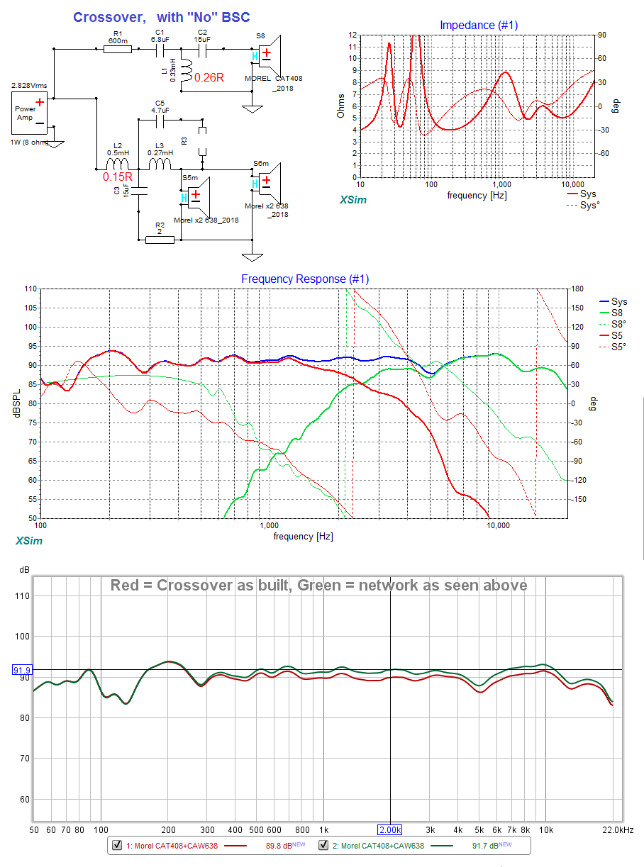
Here's a variation on your new crossover.
I've removed all the BSC ( Baffle Step Compensation ) .
It increases the component levels ( above 1K ) by close to 1.5 - 2db .
This version would definitely be "more forward sounding".
It's possible ( given your lively room acoustics ) that you may like it more ( if the current one is found to be "too polite") .
Attachments
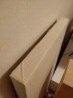
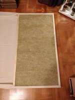
A couple of months ago I bought some 70mm 60x120cm ground insulation material. A couple of weeks after that I bought some 28x70mm wood. A couple of weeks after that I cut them to size and the day after that I assembled two 60x120cm frames. A little over a week after that (today) I went to Ikea and bought some cloth to wrap the frames with. Only bought enough for one layer for one frame since I have no idea how to get the corners nice and tidy so I figured I'd do a test run on one frame first. Turned out pretty okay, at least for the part you can see. The back side is not so pretty though. Also, it turns out that the cheapest cloth at Ikea matches the colour of my walls really well.
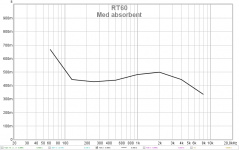
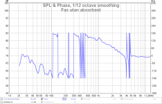
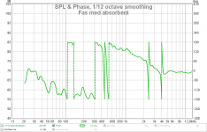
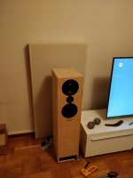
Did some measurements with and without the frame behind the left speaker. Mic was at ~1m on-axis and only left speaker was used for the measurement. Not a big difference in SPL but phase seems a little more tidy and RT60 is a little lower too.
I will wait with listening tests until I get both frames done. I will wrap this one with another layer of cloth to prevent particles from the insulation from becoming airborne and also to not have the frame "shine through" the cloth.
I will have one slab of insulation left (bought a pack of three) and I don't know what to do with it. I could build another frame but I have no idea where to put it. It would be too heavy I think for hanging it on a wall but I guess I could maybe make some space right behind the TV although I'm not sure how much it would help if placed there.
Attachments
-
 RT60(T20) med absorbent.png22.6 KB · Views: 32
 -
 Fas utan absorbent.png41 KB · Views: 39
 -
 Fas med absorbent.png40.6 KB · Views: 34
 -
 SPL.png32.4 KB · Views: 47
 -
 IMG_20190110_171820.jpg262.8 KB · Views: 47
 -
 IMG_20190110_171812.jpg277.2 KB · Views: 58
 -
 IMG_20190110_165351.jpg343 KB · Views: 38
 -
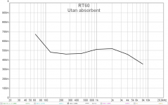 RT60(T20) utan absorbent.png22 KB · Views: 35
Thinking of getting the measurements done this week. However, the living room has changed a little since last time and the new table is not as portable and easy to move as the old one.

Where would it be best to place the speaker? Do I need to measure both or is it enough to measure just one? Can I use my absorber panels in any way to make the measurement more accurate? Shall I measure woofers only, tweeter only, and all drivers together? Mic placement 1m on-axis to tweeter?
Where would it be best to place the speaker? Do I need to measure both or is it enough to measure just one? Can I use my absorber panels in any way to make the measurement more accurate? Shall I measure woofers only, tweeter only, and all drivers together? Mic placement 1m on-axis to tweeter?
Niklas.
I suspect that you should ask your questions about room treatment within the diyaudio Room Acoustics Forum
I suspect that you should ask your questions about room treatment within the diyaudio Room Acoustics Forum
Niklas.
I suspect that you should ask your questions about room treatment within the diyaudio Room Acoustics Forum
Yes, but I'm wondering about how to measure the new crossovers correctly.
Yes, but I'm wondering about how to measure the new crossovers correctly.
Those crossovers were designed for listening ( +/- 10 deg ) to the tweeter 0-deg axis.
Measure 1M or 2M away, on axis to the tweeter.
If you want to measure ( without room effects spoiling the data ) then you have to measure outside ( at least ) 3M off the ground ( with little to know support structure contaminating the measurements ).
Alright, good design choice since I never listen on-axis
I'll see what measurement I can come up with now within the room. Outside measurements will have to wait till the weather gets warmer.
- Status
- This old topic is closed. If you want to reopen this topic, contact a moderator using the "Report Post" button.
- Home
- Loudspeakers
- Multi-Way
- New crossover for my current speakers