Hello!
I would like to build myself a pair of TL speakers! That seemed pretty easy at first, I read how people thought designing them wasn't very complicated. Speed of sound, herz, cone area and easy as pie.
Well. No.
The more I read, the less I understand! So here I am now asking for help with designing those magic unicorn speakers.
I'll try to give as much info as possible about the room conditions and so on.
The room is 4 x 5 meters (some 13 x 16 feet) with 2,2ish meters (7 feet) floor to cieling. The speakers will have to be placed about 3m (10 feet) from eachother, and listening distance will be about 3,5m. The wall the speakers face is a "log-wall" with the actual logs of the wall visible, so it's very uneven. The only furniture along that wall is the couch I'll be sitting on when listening.
I have 3-way speakers in mind, using Monacor elements. A 12" SPH-300KE as woofer, 6,5" SPH-165KEP as midrange and 1" DT-350NF as tweeter.
Woofer specs
Impedence (Z) 8ohm
Resonant frequency (fs) 22Hz
Max frequency range f3-2200Hz
Music power 200W max
Power rating (P) 120W rms
SPL (1W/1m) 90dB
Suspension compl. (Cms) 0,81mm/N
Moving mass (Mms) 65g
Mech. Q factor (Qms) 4.15
Electr. Q factor (Qes) 0.36
Total Q factor (Qts) 0.33
Equivalent volume (Vas) 250l
DC resistance (Re) 6,2ohm
Force factor (BxL) 12,5Tm
Voice coil induct. (Le) 1,5mH
Voice coil diameter 65,5mm
Voice coil former Glass fibre
Linear excursion (Xmax) +-6,5mm
Eff. cone area (Sd) 496cm2
Magnet weight 1,2kg+79g
Weight 5,4kg
I have KMTech 24dB/oct active filters allowing me to set the crossovers as I please. Active speakers powered by LM3886, one each for mids and tweeters, two each for woofers. Fed by XLR from a JC-80 clone.
From an esthetical view I like tall, not very wide but deep enclosures.
I'm not sure how much of this is actually relevant, but what I do know is that I'm fed up with banging my head against the wall trying to figure out how to design the speakers by myself. Hopefully you guys got a moment to help me out.
Regards, Andreas
Hi Andreas,
TL design is not that easy and I'm not an expert. But let's start simple, with a conventional vented loudspeaker design. Attached is an overview of possible alignments for the Monacor SPH-300 KE. The volume Vb ranges from 80 to 300 liters, but if we ignore the exotic cases, we normally choose 110-150 liters and get a cutoff frequency F3 of around 30 Hz.
That's already quite a large box and 30 Hz is probably more than enough.
A TL design usually is chosen in order to extend the range towards lower frequencies. Even though the list shows vented alignments, it is also a rough estimate of what can be expected from a transmission line. A volume of 220-300 liters and an F3 down to 20 Hz.
So the first question is, do you really need such a low corner frequency and are you willing to build such a large box?")
TL design is not that easy and I'm not an expert. But let's start simple, with a conventional vented loudspeaker design. Attached is an overview of possible alignments for the Monacor SPH-300 KE. The volume Vb ranges from 80 to 300 liters, but if we ignore the exotic cases, we normally choose 110-150 liters and get a cutoff frequency F3 of around 30 Hz.
That's already quite a large box and 30 Hz is probably more than enough.
A TL design usually is chosen in order to extend the range towards lower frequencies. Even though the list shows vented alignments, it is also a rough estimate of what can be expected from a transmission line. A volume of 220-300 liters and an F3 down to 20 Hz.
So the first question is, do you really need such a low corner frequency and are you willing to build such a large box?
Attachments
Hello!
I would like to build myself a pair of TL speakers! That seemed pretty easy at first, I read how people thought designing them wasn't very complicated. Speed of sound, herz, cone area and easy as pie.
Well. No
Greets!
They really are once you learn some fundamentals of TL, and nowadays, T/S theory. That said, MJK took all the fun out of TL design over a decade ago for those 'not practiced in the art', so either follow the instructions or use the provided Excel program:
http://www.quarter-wave.com/TLs/Alignment_Tables.pdf
http://www.quarter-wave.com/TLs/Alignment_Tables_Calculator_3_3_09.xls
All that's left then is to choose its tuning with ~25 Hz for a TL's version of a T/S max flat alignment and damp to 'taste'.
GM
Download (if you haven`t already) a piece of software called Transmission Line. You can play with it and explore different setups. The Monacor is a nice woofer but its Qts is better suited for a ported enclosure (it doesn`t mean it won`t do well in a TL). If you haven`t bought the driver yet, perhaps you may also want to explore the possibility to use two smaller woofers instead of one large? If you position them correctly, you can equalize the ripples in the response of the TL and will be able to compensate for the baffle step loss by rolling the lower woofer around the transition frequency.
I gave up on transmission lines for anything larger than 8" as the line gets too long and the final cab, well, not very enjoyable for many. If done correctly, however, they do reward the hassle.
I gave up on transmission lines for anything larger than 8" as the line gets too long and the final cab, well, not very enjoyable for many. If done correctly, however, they do reward the hassle.
Thanks for the replies!
I've been fooling around a bit with the info GM gave me, and yeah transmission lines sure are big.
1017 cm2 pipe that's 2,86m long, 290ish liters for 30Hz, if I remember correctly. I guess I could do that
but it wouldn't be easy to get the wife to accept those giants in the livingroom.
Sadly I haven't been able to find the program Mario mentioned but his idea of dual smaller woofers sounds
nice, however I guess the Vb would end up about the same.
I don't NEED silly low frequencies. I won't be using my speakers for movies - just music. So what Dissi
pointed out makes a lot of sense. Good ol' vented box. That's when I started to get silly wondering what
else I could get for about the same money as the SPH-300KE.
Dual 10" SPH-250TC
Dual 12" SPH-300TC
Or a 15" SPH-390TC
However, I don't JUST want loud, I want it to sound good. I'm going through the trouble of building myself
a pair of JC-80 clones and I don't want to ruin the overall sound quality by choosing the wrong woofers.
I listen mostly to industrial/EBM music and I'm no "true" audiophile so I'm not rediciously picky.
I haven't given up on TL but to be perfectly honest, becouse of size I'll probably end up with vented.
What's that fancy software you use, Dissi?
Using the T/S specs provided by the OP, I modeled a tapered line 70" long and tapered at 15:1, having a beginning cross-section of 16"W x 15"D and an ending area of 16"W x 1"D. The woofer's center was located 14" from the beginning of the line. Without any stuffing the line's 1/4-wavelength resonant frequency tunes the system to 24 Hz, and this drops a couple of Hz with the first 2/3 of the line stuffed at 0.75 lb/ft3. The resulting f3 was a smidgen above 30 Hz and the response was all but flat from the knee in the curve up to 1 kHz (the limits of Martin King's software). The line's volume is ~150 liters.
Paul
Paul
TLines are not space efficient and they rarely get deeper than vented, even in a larger box. They also have nulls in the response and have a 4th order rolloff just like a vented. Transient response is also not likely any better than vented.
Before I saw Dissi's post I modeled a 130liter vented enclosure tuned to 27Hz and got an F3 of 28Hz. 10.2cm diameter vent, 18.3cm long.
Before I saw Dissi's post I modeled a 130liter vented enclosure tuned to 27Hz and got an F3 of 28Hz. 10.2cm diameter vent, 18.3cm long.
TLines … have a 4th order rolloff just like a vented
That all depends on how they are stuffed.
dave
Sadly I haven't been able to find the program Mario mentioned but his idea of dual smaller woofers sounds
nice, however I guess the Vb would end up about the same.
Reason is his website is down by some reason. There i an offline installer here - http://www.diyaudio.com/forums/soft...n-line-modelling-software-81.html#post5160274
Dual smaller woofers would allow you to reduce the amount of stuffing because they can offset the line ripples caued by each if spaced orrectly. You have ot experiment but usually putting the drivers at 1/3 and 1/5 of the line length does the trick but sometimes they need to be spaced differently. With reduced stuffing, you will get more low end output.
you know there is wilmslow audio providing you with fully calculated and CNC'd TL cabinets?
3 way Transmission-line cabinets
all you have to do is gluing it together and give it a paint of choice
3 way Transmission-line cabinets
all you have to do is gluing it together and give it a paint of choice
Your suggestion on using two drivers spaced apart sounds like it's bit of a "by guess and by gosh" process, meaning you can't model it to know what you're likely to get. I'd much rather use an accurate modeling program, like Martin King's, because if the modeled design looks to have good performance and I build exactly what I modeled, it will have good performance. Using less stuffing, either in density or length, will definitely lower f3, but it's not a lot and the difference is audibly not very much.
Paul
Paul
Reason is his website is down by some reason. There i an offline installer here - http://www.diyaudio.com/forums/soft...n-line-modelling-software-81.html#post5160274
Dual smaller woofers would allow you to reduce the amount of stuffing because they can offset the line ripples caued by each if spaced orrectly. You have ot experiment but usually putting the drivers at 1/3 and 1/5 of the line length does the trick but sometimes they need to be spaced differently. With reduced stuffing, you will get more low end output.
Modeling graphs
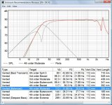
Just wanted to follow up on the modeling I did as described in Post #7. I've attached 3 modeling graphs. The first one shows the predicted anechoic system bass response (red line) without any stuffing in the 15:1 tapered line where you can see that f3 is ~27 Hz (the system tuning is 24 Hz from the line's 1/4-wavelength resonant frequency). The second graph shows the response (red line) after stuffing is added as I described in Post #7, and you can see that f3 has now increased slightly to 30 Hz (the system tuning frequency has decreased to 22 Hz). The last graph shows the air velocity in the terminus as a percentage of the speed of sound, peaking at 1.6% (5.5 m/s) at ~18 Hz. This modeling shows the predicted response for an input of 35w/1m which is the power required to cause an excursion of the woofer to its Xmax rating, which it first reached at ~33 Hz.
Paul
Attachments
You can model them one by one by changing the location and then comparing the two graphs so the peaks and dips are matched to whatever extent possible. But you are right that there is uncertainty in this approach as I do not know how the woofers would affect each other when operating simultaneously loading the same line, not until I have built it. AFAIK, the program done by Len is based on the same formulas as the sheets you`re using, but it has a nie graphic interface and does not require a MathCAD license.
Careful tap location of a driver (or driver pair) into the line at a single given point should eliminate the need for a large physical separation between the two. A closely mounted driver pair effectively behave (as far as the line is concerned) as a single unit and it is not difficult to optimise this to minimise unwanted excititation of harmonic modes without needing to resort to anything more complicated. Separating the drivers out & tapping them into significantly different points in the line can work if properly designed, but it's not necessary from the perspective of the acoustic loading / performance of the line. There may be other factors such as marketing, overall dimensions / shape of the enclosure, external driver position / height that requires alternatives of course.
Last edited:
Keeping in mind what Scottmoose posted after you, if you had a pair of 8" woofers and a line that's 69" long, if the woofers were located at the 1/5 and 1/3 points, one of them would have its center at ~14" from the line's beginning and the other woofer's center would be at 23", for instance. It's likely, then, that the flanges of the woofers would either be touching or almost so. Therefore, if you model as if there's a single woofer at the midpoint of the woofers with twice the Vas and Sd, which works very, very well and the woofers are working in unison, you will have accomplished what you suggest and there will be no guessing or trial and error. BTW, I don't require a MathCad license because I have the free version of MathCad (Explorer 8 I think its called). It doesn't allow saving an electronic copy of any modeling that can be re-opened and worked on again, but that's a small "price" to pay.
Paul
Paul
You can model them one by one by changing the location and then comparing the two graphs so the peaks and dips are matched to whatever extent possible. But you are right that there is uncertainty in this approach as I do not know how the woofers would affect each other when operating simultaneously loading the same line, not until I have built it. AFAIK, the program done by Len is based on the same formulas as the sheets you`re using, but it has a nie graphic interface and does not require a MathCAD license.
Assuming the woofer's specs posted by the OP are reasonably representative, I used them and the predicted performance of the TL I modeled looks quite good to me.
Paul
Paul
Doesnt look like the woofer parameters wd suit a TL.
I thought I should add that for a pair of woofers closely located to each other, flange to flange essentially, I'd always use their midpoint as the TL's modeling center, locating it at either the 1/5 or 1/3 point along the line's length (or nearly so, at least) and not worry about each woofer's center not being exactly at either of these optimum locations.
Paul
Paul
Keeping in mind what Scottmoose posted after you, if you had a pair of 8" woofers and a line that's 69" long, if the woofers were located at the 1/5 and 1/3 points, one of them would have its center at ~14" from the line's beginning and the other woofer's center would be at 23", for instance. It's likely, then, that the flanges of the woofers would either be touching or almost so. Therefore, if you model as if there's a single woofer at the midpoint of the woofers with twice the Vas and Sd, which works very, very well and the woofers are working in unison, you will have accomplished what you suggest and there will be no guessing or trial and error. BTW, I don't require a MathCad license because I have the free version of MathCad (Explorer 8 I think its called). It doesn't allow saving an electronic copy of any modeling that can be re-opened and worked on again, but that's a small "price" to pay.
Paul
if you model as if there's a single woofer at the midpoint of the woofers with twice the Vas and Sd, which works very, very well
An example of this. A woden specified ML-TL. It does work very, very well. F10 near 25 Hz.
dave
- Status
- This old topic is closed. If you want to reopen this topic, contact a moderator using the "Report Post" button.
- Home
- Loudspeakers
- Multi-Way
- Help needed with TL calculation