The ear is remarkably insensitive to absolute phase (relative phase is important at crossover, or between stereo channels, because relative phase impacts the magnitude when 2 or more signals are summed), which means the ear is also remarkably insensitive to the "shape" of the time-domain impulse response.
Of course, there are arguments to the contrary. People are more sensitive to phase and absolute phase at lower frequencies, particularly for percussive sounds. Some people probably more so than others. Maybe most of that is below frequencies at which a line array would be operated?
Very reasonable points ... on all counts.Of course, there are arguments to the contrary. People are more sensitive to phase and absolute phase at lower frequencies, particularly for percussive sounds. Some people probably more so than others. Maybe most of that is below frequencies at which a line array would be operated?
POST #18
D. Infinite Line Source: time-domain impulse response (continued)
The time-domain impulse response for our Infinite Line Source is :
h(t) = (rho/2pi)*INT[(1/R)*delta[t - R/c]]dz, from z = 0 to +infinity
where "R" is a function of the integration variable, "z" :
R = sqrt[r^2 + z^2]
And we recognize that the impulse response is simply the continuous sum of the weighted and delayed impulses from all of the little "dz" elements that form our infinite line") All we need to do, is solve this integral ...
All we need to do, is solve this integral ...
Given the presence of the delta function inside the integral, we'd like to get the integral in the form of :
INT[ f(v)*delta[t - v] ]dv
so that we can exploit the "sampling property" of the delta function (discussed earlier in this thread, POST #4).
So, let's perform a straightforward substitution of variables :
v = R/c = {sqrt[r^2 + z^2]}/c
from which it immediately follows that :
z = sqrt[(cv)^2 - r^2]
dv/dz = z/{c*sqrt[r^2 + z^2]}
dz/R = (c/z)*dv
and the integration limits in the new variable "v" are :
z = 0 ======> v = r/c
z = infinite ===> v = infinite
Our time-domain impulse response for the Infinite Line Source is now given by this new integral in "v":
h(t) = (rho/2pi)*INT[ c*delta[t - v]/sqrt[(cv)^2 - r^2] ]dv, from v = r/c to v = +infinity
we're almost done ...
D. Infinite Line Source: time-domain impulse response (continued)
The time-domain impulse response for our Infinite Line Source is :
h(t) = (rho/2pi)*INT[(1/R)*delta[t - R/c]]dz, from z = 0 to +infinity
where "R" is a function of the integration variable, "z" :
R = sqrt[r^2 + z^2]
And we recognize that the impulse response is simply the continuous sum of the weighted and delayed impulses from all of the little "dz" elements that form our infinite line
All we need to do, is solve this integral ...Given the presence of the delta function inside the integral, we'd like to get the integral in the form of :
INT[ f(v)*delta[t - v] ]dv
so that we can exploit the "sampling property" of the delta function (discussed earlier in this thread, POST #4).
So, let's perform a straightforward substitution of variables :
v = R/c = {sqrt[r^2 + z^2]}/c
from which it immediately follows that :
z = sqrt[(cv)^2 - r^2]
dv/dz = z/{c*sqrt[r^2 + z^2]}
dz/R = (c/z)*dv
and the integration limits in the new variable "v" are :
z = 0 ======> v = r/c
z = infinite ===> v = infinite
Our time-domain impulse response for the Infinite Line Source is now given by this new integral in "v":
h(t) = (rho/2pi)*INT[ c*delta[t - v]/sqrt[(cv)^2 - r^2] ]dv, from v = r/c to v = +infinity
we're almost done ...
POST #19
D. Infinite Line Source: time-domain impulse response (continued)
time-domain impulse response :
h(t) = (rho/2pi)*INT[ c*delta[t - v]/sqrt[(cv)^2 - r^2] ]dv, from v = r/c to v = +infinity
thanks to the "sampling property" of the delta function :
h(t) = (rho/2pi)*INT[ c*delta[t - v]/sqrt[(ct)^2 - r^2] ]dv, from v = r/c to v = +infinity
pulling all terms with no "v" dependency outside the integral :
h(t) = (rho/2pi)*{c/sqrt[(ct)^2 - r^2]} * INT[delta[t - v]]dv, from v = r/c to v = +infinity
The remaining integral in the above expression is now quite trivial
Note the lower limit of the integration variable, "r/c". The delta function inside that integral means that :
For t<(r/c): the argument of the delta function is less than zero for all included "v" ... and so the integral = 0.
For t>(r/c): the v-integral 'sweep' of the delta function will 'trigger' the impulse ... and so the integral = 1.
Which means that the remaining integral in the above expression = u[t - r/c]
(where u[t] is the unit step function)
re-arranging a few terms, leaves us with the wonderful result we've been seeking :
h(t) = (rho/2pi) * {u[t - r/c]/sqrt[t^2 - (r/c)^2]}
where:
r = distance from the Infinite Line Source to our measurement point
we can simplify even further, and re-express :
Let Td = (r/c), so that Td is the 'perpendicular' (or shortest) time delay from the Infinite Line Source to our measurement point:
h(t) = 0, for t<Td
h(t) = rho/{2pi*sqrt[t^2 - (Td)^2]}, for t>Td
THIS ^^ is the time-domain impulse response for an Infinite Line Source
one or two more posts, and the "tutorial" section of the thread is done
POST #19a
D. Infinite Line Source: time-domain impulse response (continued)
A slightly different form for the time-domain impulse response ... i like this one even better :
h(t) = 0, for T<Td
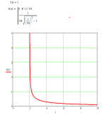
h(t) = rho/{2pi*Td*sqrt[(t/Td)^2 - 1]}, for t>Td
where Td = 'perpendicular' (or shortest) time delay from the Infinite Line Source to our measurement point.
D. Infinite Line Source: time-domain impulse response (continued)
A slightly different form for the time-domain impulse response ... i like this one even better :
h(t) = 0, for T<Td
h(t) = rho/{2pi*Td*sqrt[(t/Td)^2 - 1]}, for t>Td
where Td = 'perpendicular' (or shortest) time delay from the Infinite Line Source to our measurement point.
Perhaps someone can post some plots of the time-domain impulse response from POST #19a, for a few values of Td ... maybe Td = 1, 2, 5, 10Graphs soon?
... where (rho/2pi) can be 'normalized' to unity (or any other convenient value). The impulse response "tail" will be immediately apparent. Please note that:
1/{Td*sqrt[(t/Td)^2 - 1]} ~ 1/t (for t >> Td)
And please remember ... the time-domain impulse response is simply the Inverse Fourier Transform of the frequency-domain transfer function (aka frequency response). One is completely determined by the other ... the same information is presented in either domain, time or frequency. For the Infinite Line Source ... we see ~ 3dB drop for every doubling of frequency and/or distance in the frequency domain, which dictates (or, is dictated by) ~ 1/t behavior in the time domain.
Perhaps someone can post some plots of the time-domain impulse response
Done
I think that I'll show the finite cylindrical source in Mathcad also as it makes for a nice clean presentation.
Attachments
Last edited:
Thank you Earl !!!
Guys (and girls), i really need to explore something in yet another 'sidebar'. The issue i want to discuss, briefly, is triggered by an observation of UNITS.
If you look at the impulse response (presented in its most compact form in POST #19a), you'll notice (ignore the "rho" term, for now) that the units are "1/(time)". What's up with that? Is that even right?
The answer is ... YES, it's right
The Dirac impulse ... delta(t) ... is really a mathematical abstraction, defined more by its integral than anything. When you integrate the Dirac impulse, over time, you get something with real, physical meaning ... namely, the unit step function ... u(t). It's not really "wrong", then, to consider that the "units" of the Dirac impulse itself are "1/(time)".
A simple, familiar example : consider the simple 1st-order RC low pass filter. When you examine the mathematical form of the step-response, you'll find the classic exponential rise, asymptotically approaching the value of 1 ... unitless "one" (or, the step response will have units of "volts" if the input step-function has units of "volts"). What does the mathematical formulation of the impulse-response look like? Recognizing that differentiation and integration are linear operators, whose operations are "preserved" across linear systems, we can answer that by taking the first derivative (wrt time) of the step response We'll find another exponential ... asymptotically approaching zero ... but now, with units of (1/time). YES, the time-domain impulse response of the simple RC low-pass filter ALSO has units of (1/time).
... just another reason why studying digital signal processing BEFORE analog signal processing makes sense The first was the concept of convolution, which is really easy to understand in the discrete-time domain but too damn abstract in the continuous-time domain And now, we find ourselves dealing with the abstract nature of the Dirac impulse yet again, in something as seemingly straightforward as "impulse response".
If anyone is interested, we can develop the time-domain STEP response of an Infinite Line Source (by simply integrating, in time, the impulse response) ... to reveal something a bit more practical or "tangible", with units that make physical sense ...
Guys (and girls), i really need to explore something in yet another 'sidebar'. The issue i want to discuss, briefly, is triggered by an observation of UNITS.
If you look at the impulse response (presented in its most compact form in POST #19a), you'll notice (ignore the "rho" term, for now) that the units are "1/(time)". What's up with that? Is that even right?
The answer is ... YES, it's right
The Dirac impulse ... delta(t) ... is really a mathematical abstraction, defined more by its integral than anything. When you integrate the Dirac impulse, over time, you get something with real, physical meaning ... namely, the unit step function ... u(t). It's not really "wrong", then, to consider that the "units" of the Dirac impulse itself are "1/(time)".
A simple, familiar example : consider the simple 1st-order RC low pass filter. When you examine the mathematical form of the step-response, you'll find the classic exponential rise, asymptotically approaching the value of 1 ... unitless "one" (or, the step response will have units of "volts" if the input step-function has units of "volts"). What does the mathematical formulation of the impulse-response look like? Recognizing that differentiation and integration are linear operators, whose operations are "preserved" across linear systems, we can answer that by taking the first derivative (wrt time) of the step response
We'll find another exponential ... asymptotically approaching zero ... but now, with units of (1/time). YES, the time-domain impulse response of the simple RC low-pass filter ALSO has units of (1/time).... just another reason why studying digital signal processing BEFORE analog signal processing makes sense
The first was the concept of convolution, which is really easy to understand in the discrete-time domain but too damn abstract in the continuous-time domain And now, we find ourselves dealing with the abstract nature of the Dirac impulse yet again, in something as seemingly straightforward as "impulse response".If anyone is interested, we can develop the time-domain STEP response of an Infinite Line Source (by simply integrating, in time, the impulse response) ... to reveal something a bit more practical or "tangible", with units that make physical sense ...
Last edited:
POST #20
thoughts and observations
When we developed the frequency response and impulse response for the idealized Point Source, we found what i've called "faithful spherical radiation" (Post #6). There are two (2) components to the Point Source radiation that lead us to this conclusion : first, there's a "spherical symmetry" to the radiation ... meaning, the pressure measured at any point on a sphere (with point source at the center) is the same; second, the time-domain impulse response (measured at any point on the sphere) is itself an impulse, simply delayed and attenuated as the distance from the single point-source increases. The fact that the impulse response is, itself, impulsive ... means that the frequency response (magnitude) is perfectly flat, at any point on the measuring sphere.
Our idealized Infinite Line Source behaves quite differently, of course. It displays what i'll call "dispersive cylindrical radiation". The corresponding two (2) components to the Infinite Line Source radiation are : first, the radiation displays "cylindrical symmetry" ... meaning, the pressure measured at any point on an infinite cylinder (with line source along the center axis) is the same; but second, the time-domain impulse response (measured at any point on the cylinder) is NOT impulsive. Rather, the impulse response displays a "tail" resulting from the single measuring point receiving a continuous signal ... each part being a delayed and attenuated response from all elements that form the infinite line. The fact that the impulse response is NOT impulsive ... means that the frequency response (magntiude), at any point on the measuring cylinder, is NOT flat.
So why bother? Why bother analyzing line sources (infinite or finite), and why bother building anything similar? Anything even approaching an Infinite Line Source will need some serious equalization ... quite possibly, something close to +3dB per octave (not trivial!). Why bother?
There are two (2) fundamental merits to line sources, as i see it :
1. The "-3dB per doubling-of-distance" is hard to ignore, in my opinion (compared to "-6dB per doubling-of-distance" for a point source). It means, at least, the possibility of a wider "sweet spot" for stereo listening.
2. Chances are, whatever "line source" we may build will be composed of a long line (or array) of small-ish drivers. Each driver will have to work "less hard" for a given SPL ... meaning, the possibility of lower distortion, lower power compression, etc.
Which will lead us to my last post in the so-called "tutorial": some practical considerations (including, how we might "build" something that's infinitely long!) a topic which i can only introduce, and then invite all others to share their knowledge and experience
thoughts and observations
When we developed the frequency response and impulse response for the idealized Point Source, we found what i've called "faithful spherical radiation" (Post #6). There are two (2) components to the Point Source radiation that lead us to this conclusion : first, there's a "spherical symmetry" to the radiation ... meaning, the pressure measured at any point on a sphere (with point source at the center) is the same; second, the time-domain impulse response (measured at any point on the sphere) is itself an impulse, simply delayed and attenuated as the distance from the single point-source increases. The fact that the impulse response is, itself, impulsive ... means that the frequency response (magnitude) is perfectly flat, at any point on the measuring sphere.
Our idealized Infinite Line Source behaves quite differently, of course. It displays what i'll call "dispersive cylindrical radiation". The corresponding two (2) components to the Infinite Line Source radiation are : first, the radiation displays "cylindrical symmetry" ... meaning, the pressure measured at any point on an infinite cylinder (with line source along the center axis) is the same; but second, the time-domain impulse response (measured at any point on the cylinder) is NOT impulsive. Rather, the impulse response displays a "tail" resulting from the single measuring point receiving a continuous signal ... each part being a delayed and attenuated response from all elements that form the infinite line. The fact that the impulse response is NOT impulsive ... means that the frequency response (magntiude), at any point on the measuring cylinder, is NOT flat.
So why bother? Why bother analyzing line sources (infinite or finite), and why bother building anything similar? Anything even approaching an Infinite Line Source will need some serious equalization ... quite possibly, something close to +3dB per octave (not trivial!). Why bother?
There are two (2) fundamental merits to line sources, as i see it :
1. The "-3dB per doubling-of-distance" is hard to ignore, in my opinion (compared to "-6dB per doubling-of-distance" for a point source). It means, at least, the possibility of a wider "sweet spot" for stereo listening.
2. Chances are, whatever "line source" we may build will be composed of a long line (or array) of small-ish drivers. Each driver will have to work "less hard" for a given SPL ... meaning, the possibility of lower distortion, lower power compression, etc.
Which will lead us to my last post in the so-called "tutorial": some practical considerations (including, how we might "build" something that's infinitely long!)
a topic which i can only introduce, and then invite all others to share their knowledge and experience
Last edited:
Have any of you pondered over the fact that mics are small, not seldom omnidirectional but a line source is eee... a line and large. What about some symmetry between the recording and replay functions in the electro-acoustcal interfaces? Is that even important? Maybe we shall invent looong ribbon mics?
//
//
I've been meaning to comment on the -6 dB per doubling of distance for the point source. In short: it doesn't happen in a room. As we get farther from the source, the ratio between the direct path length and the reflected path lengths gets smaller. Although the direct path may fall off at 6 dB per doubling, the reflections are falling off at less than that. The actual change in apparent loudness will be something other than -6 dB per doubling, but will depend on the room geometry, the floor and wall materials, etc.
hmmmm ... i'm not just blowing wind up your skirt, this is an interesting question, worthy of some thought i think ...Have any of you pondered over the fact that mics are small, not seldom omnidirectional but a line source is eee... a line and large. What about some symmetry between the recording and replay functions in the electro-acoustcal interfaces? Is that even important? Maybe we shall invent looong ribbon mics?
//
Earl, thanks again for your participation in our little threadWe will come back to this later, but it has always been my opinion that the speakers should be point sources for much the same reasons that you mention. A point source with directivity, that's my goal.
You're not really done making speakers, are you?I have to admit to a certain fascination ... after ~90 years of sound reproduction, and ~60 years of stereo reproduction ... there's STILL a healthy debate about whether our loudspeakers should "mimic" ideal points, or ideal lines ...
Thanks, valid point. Of course, we may find that line sources display less than -3dB per doubling-of-distance, in real rooms, as well ...I've been meaning to comment on the -6 dB per doubling of distance for the point source. In short: it doesn't happen in a room. As we get farther from the source, the ratio between the direct path length and the reflected path lengths gets smaller. Although the direct path may fall off at 6 dB per doubling, the reflections are falling off at less than that. The actual change in apparent loudness will be something other than -6 dB per doubling, but will depend on the room geometry, the floor and wall materials, etc.
Let's take a moment (yes another sidebar) to quickly develop the time-domain step response for the Infinite Line Source (to reveal a meaningful response with not-so-abstract units)
The impulse response (from POST #19a) is :
h(t) = 0, for T<Td
h(t) = rho/{2pi*Td*sqrt[(t/Td)^2 - 1]}, for t>Td
Linear Time-Invariant systems really are wonderful things Given some input, x, that creates some output, y ... how do we find the output for an input equal to the derivative of x? Simple! We just take the derivative of y The same holds true for integration ... differentiation and integration are linear operators, whose operations are "preserved" across LTI systems.
Since the unit step input, u(t), is the integral (wrt time) of the impulse input, delta(t) ... we can find the step response by simply integrating the impulse response. Let g(t) be the step response of the Infinite Line Source :
g(t) = INT[h(t)]dt, from t = -infinity to +infinity
I'll spare everyone the details of the integration (really just a trivial change of variables, to express in a form found in integration tables), and just state the result :
g(t) = 0, for t<Td
g(t) = (rho/2pi) * ln[ (t/Td) + sqrt[(t/Td)^2 - 1] ], for t>Td
where :
ln[x] = "natural log" of x
Td = perpendicular (shortest) time delay from line source to measurement point
(the result is most readily verified by proving that: dg(t)/dt = h(t) )
(to reveal a meaningful response with not-so-abstract units)The impulse response (from POST #19a) is :
h(t) = 0, for T<Td
h(t) = rho/{2pi*Td*sqrt[(t/Td)^2 - 1]}, for t>Td
Linear Time-Invariant systems really are wonderful things
Given some input, x, that creates some output, y ... how do we find the output for an input equal to the derivative of x? Simple! We just take the derivative of y The same holds true for integration ... differentiation and integration are linear operators, whose operations are "preserved" across LTI systems.Since the unit step input, u(t), is the integral (wrt time) of the impulse input, delta(t) ... we can find the step response by simply integrating the impulse response. Let g(t) be the step response of the Infinite Line Source :
g(t) = INT[h(t)]dt, from t = -infinity to +infinity
I'll spare everyone the details of the integration (really just a trivial change of variables, to express in a form found in integration tables), and just state the result :
g(t) = 0, for t<Td
g(t) = (rho/2pi) * ln[ (t/Td) + sqrt[(t/Td)^2 - 1] ], for t>Td
where :
ln[x] = "natural log" of x
Td = perpendicular (shortest) time delay from line source to measurement point
(the result is most readily verified by proving that: dg(t)/dt = h(t) )
hmmmm ... i'm not just blowing wind up your skirt, this is an interesting question, worthy of some thought i think ...
I'm currently in the process of building a microphone array. I've been working out the details slowly over the last several months, and started ordering parts about 5 or 6 weeks ago. I'm 85 or 90 percent done putting it together. My intent is to apply coherent spatial processing techniques in order to use the same array to create different channels for stereo, or even for surround. I did a quick test with a mock up (only 6 channels) months ago and found the results encouraging. I can tune how much of the room I want vs the performers. This is most applicable to large groups of performers like symphony orchestras. I don't want to derail this thread. I plan to post plenty of information about the array with sample files on youtube and gearslutz once I'm up and running. That wont be for a few weeks or more. PM me if interested.
Thanks for the offer! Sounds VERY intriguing ... I'll read your threads and info, when they're ready for "public consumption"I'm currently in the process of building a microphone array. I've been working out the details slowly over the last several months, and started ordering parts about 5 or 6 weeks ago. I'm 85 or 90 percent done putting it together. My intent is to apply coherent spatial processing techniques in order to use the same array to create different channels for stereo, or even for surround. I did a quick test with a mock up (only 6 channels) months ago and found the results encouraging. I can tune how much of the room I want vs the performers. This is most applicable to large groups of performers like symphony orchestras. I don't want to derail this thread. I plan to post plenty of information about the array with sample files on youtube and gearslutz once I'm up and running. That wont be for a few weeks or more. PM me if interested.
- Status
- This old topic is closed. If you want to reopen this topic, contact a moderator using the "Report Post" button.
- Home
- Loudspeakers
- Multi-Way
- Infinite Line Source: analysis