Hi,
After finishing two modified MTH-30's with an impressive result (for me as a noob ), I now want to take care of the upper frequencies. (from 300hz)
I would really like a Unity/Synergy style horn. I thought of something like wiliam cowan's:
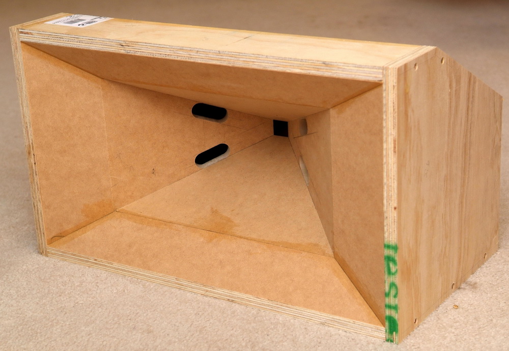
He states they would go down to 100Hz (two 8") so I think I might just need two 6" drivers. As CD I wanted to use the DE250.
- The only thing I have no idea about right now is how to calculate it with hornresp. Can someone explain that to me or link me to something?
I need to figure out the Horn expansion, The Mid placement and their entrance in to the Horn.
- How to control the directivity? (I want 60*90°)
- Also do I need to build some sort of adapter for the CD?
- Any suggestions for the 6"? (Not to expensive Should be available in europe)
Thanks in advance.
After finishing two modified MTH-30's with an impressive result (for me as a noob
), I now want to take care of the upper frequencies. (from 300hz)I would really like a Unity/Synergy style horn. I thought of something like wiliam cowan's:
He states they would go down to 100Hz (two 8") so I think I might just need two 6" drivers. As CD I wanted to use the DE250.
- The only thing I have no idea about right now is how to calculate it with hornresp. Can someone explain that to me or link me to something?
I need to figure out the Horn expansion, The Mid placement and their entrance in to the Horn.
- How to control the directivity? (I want 60*90°)
- Also do I need to build some sort of adapter for the CD?
- Any suggestions for the 6"? (Not to expensive Should be available in europe)
Thanks in advance.
You may not be getting any traction here because you are asking quite a lot. HornResp tutorials are out there if you search. I can't think of any off the top of my head. Mid placement will be set by your upper mid xo and perhaps the physical size of the driver (how close can you get it to the compression driver?). The horn expansion will be set by the directivity pattern you seek, assuming we are talking a conical horn/wg.
Not sure what you are looking for with "how to control the directivity?"? Are you asking how large should it be?
CD adapter? The DE250 has a standard bolt pattern. Since you will be building the horn you can build the cd mount onto the horn itself. No adapter will be needed. Or, are you wondering how to handle the round to square transition if you are building a rectangular conical horn?
As far as the mid driver goes a 6" is really not necessary or needed to get down to 300hz. Can you get the Celestion TF0401MR? It's a 4" closed back mid with the perfect parameters for a Synergy horn. Danley uses them in the SH50 afaik. I'm using them on my small Synergy horns and they get down to 300hz using only two mids without issue.
If you study this thread: Suitable midrange cone, for bandpass mid in Unity horn. you will find answers to all of your questions I'm sure! Might take you a while to wade through it but you ought to come away with a pretty good understanding of how these things work and how to design them.
Here's a link to bwaslo's excellent Synergy spreadsheet which you can use to design a rectangular conical Synergy (will need input from HornResp): https://www.google.com/url?sa=t&rct=j&q=&esrc=s&source=web&cd=1&cad=rja&uact=8&ved=0ahUKEwjMiPHtypnXAhVm2oMKHZXcCvoQFggqMAA&url=http%3A%2F%2Flibinst.com%2FSynergyCalc%2FSynergy%2520Calc%2520V5.pdf&usg=AOvVaw2DTdKfx2_xEJ5zB9JjdncE
Thanks for your answer!
I figured out the most stuff allready i think:
-put the mid drivers as close to the throat as possible (same for its ports)
-used the pdf to create basic horn shape
- Mid response is dependent on the Port(s) size and placement
What is "upper mid xo"?
Yeah and i meant round to rectangular adapter for the CD...
The 4" looks promising, but i can't seem to find tsp's... Any Idea? (also the rear chamber?)
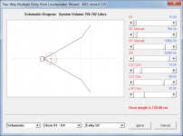
I started simming w/o RMS, CMS and with a rough guess on MMD and VRC.

Seems okay... Any Idea on how to get a little more liniarity and low end?
Greetings!
I figured out the most stuff allready i think:
-put the mid drivers as close to the throat as possible (same for its ports)
-used the pdf to create basic horn shape
- Mid response is dependent on the Port(s) size and placement
What is "upper mid xo"?
Yeah and i meant round to rectangular adapter for the CD...
The 4" looks promising, but i can't seem to find tsp's... Any Idea? (also the rear chamber?)
I started simming w/o RMS, CMS and with a rough guess on MMD and VRC.
Seems okay... Any Idea on how to get a little more liniarity and low end?
Greetings!
By upper mid xo I mean how high do you want the mid to play?
As far as the CD entrance goes I think most people start out with a square entrance and then bore it out with a 1" drill....iirc the spreadsheet has that info.
I'll see if I can dig up the T/S I used for the 4" drivers. I didn't measure them personally but found it online. I'll try to remember anyways! It's been quite a while since I used HornResp but I think better input data will improve your result. Fwiw I use two .5" dia ports per 4" driver with a roughly 1" dia countersink on the driver side.
This is what I used for the 4" Celestion sealed back mid:

This worked pretty well. BTW, the thing about getting the mid ports "as close as possible" to the throat is for when you're using a small HF compression driver that has trouble reaching down to 1kHz. If you use something like a DNA360 or a DE250, you have some leeway to put the ports out further. But usually the best place to start is with the ports down as close as the driver sizes and mounting requirements will allow you to go, you can always move them out. Try to adjust the midrange for best response, but also so that it has the least response at frequencies above the cancellation notch -- get the acoustic filter working for you instead of leaving an ugly glitch that has to be removed with the crossover.
With the Celestion 4incher you're not going to get it much below ~350Hz.
Thanks for your answers!
Experimented a little bit...

I'm happy with the result, but AP1 seems a little bit too low...
I mean: sqroot( (2.5 / 4) / pi ) *2 = 2.8mm Diameter per port ?!
Is this realistic?! Compression ratio of 29.036 seems pretty deadly to me...
Everything else I tried resulted in a bad response.
If this isn't realistic, what tips do you have to get a smooth response in this case?
@bwaslo could I see a pic of your full result? thx
And how low can I expect the DE250 to go in this horn?
Greetings!
Experimented a little bit...
I'm happy with the result, but AP1 seems a little bit too low...
I mean: sqroot( (2.5 / 4) / pi ) *2 = 2.8mm Diameter per port ?!
Is this realistic?! Compression ratio of 29.036 seems pretty deadly to me...
Everything else I tried resulted in a bad response.
If this isn't realistic, what tips do you have to get a smooth response in this case?
@bwaslo could I see a pic of your full result? thx
And how low can I expect the DE250 to go in this horn?
Greetings!
AP1 is in sq. cm.
2.8 cm is more reasonable but on the large size for a mid that covers 300 Hz++. shorten the Lp by thinning out the horn wall around the ports, creating frustrums, for shorter effective port length and you should find smaller diameter holes work
The DE250 has been used down just below 1 Khz but you might like it better XOing at 1200 Hz
Hi,
I think my mistake was, that I thought AP1 is the sum of both drivers which doesn't seem to be the case... One hole is 1,26cm now.
I like the results as they are and would like to make the plans now.
Anything you would want to change for the mid's?
Thanks for all the help!
I think my mistake was, that I thought AP1 is the sum of both drivers which doesn't seem to be the case... One hole is 1,26cm now.
I like the results as they are and would like to make the plans now.
Anything you would want to change for the mid's?
Thanks for all the help!
I think my mistake was, that I thought AP1 is the sum of both drivers which doesn't seem to be the case...
Just to clarify - Ap1 is the total area for both drivers.
If Ap1 = 2.5 cm^2 then for each driver the throat chamber port area is 2.5 / 2 = 1.25 cm^2, the radius is (1.25 / Pi) ^ 0.5 = 0.63 cm and the diameter is 0.63 * 2 = 1.26 cm.
The value of 1000 litres specified for Vrc seems very large (equivalent to a cube having a side length of 1 metre).
The two-way Unity horn should really be modelled as a multiple entry horn system, rather than as an offset driver horn system, so that the high frequency driver at the apex throat is also taken into account.
Attachments
Ok, that's what I thought in the first place...
As I have 2 ports per driver I now get 0,892062058076386cm Diameter per port... (My first calculation was entered false in to the iPhone calculator)
I used VRC =1... I think he put in 1000cm^2.
will try the ME horn when I'm home
Thanks!
As I have 2 ports per driver I now get 0,892062058076386cm Diameter per port... (My first calculation was entered false in to the iPhone calculator)
I used VRC =1... I think he put in 1000cm^2.
will try the ME horn when I'm home
Thanks!
David -- the huge value for Vrc is because this is a sealed back driver, it's compliance is already determined by its built-in sealed back in its measurements. I made Vrc large because I didn't want that compliance reduced further by another back volume (that would really have no effect since the compliance is as low as it will ever be).
Is that not the right way to do that?
Is that not the right way to do that?
As I have 2 ports per driver I now get 0,892062058076386cm Diameter per port...
Your calculation is correct
.David -- the huge value for Vrc is because this is a sealed back driver, it's compliance is already determined by its built-in sealed back in its measurements. I made Vrc large because I didn't want that compliance reduced further by another back volume (that would really have no effect since the compliance is as low as it will ever be).
Is that not the right way to do that?
Hi Bill,
For your design, what you did makes complete sense.
I did not realise that MrOIL also intended using sealed-back drivers
.Kind regards,
David
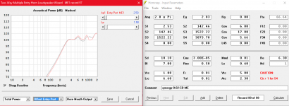
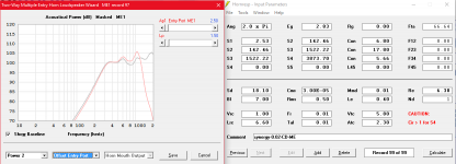
I simmed it with ME now...
Pictures:
1 - synergy 3: Grey: normal, Red: 1300Hz 4th order Crossover
2 - synergy 4: Red: only Mid's
(The DE250 sim isn't accurate at all I think)
This is the best I could come up with... What do you think?
I want to build this thing after Christmas and I really don't wanna build ****!
Thanks in advance!
Attachments
Have you modeled the internal acoustic path of the CD? The sound penetrates into the CD some distance into the CD and reflects off its phase plug to cause a reflection null that limits mid bandwidth. I'm not sure what the distance is for the DE250. I would guess around 3 cm. If you can increase L12 by 3cm and still have adequate mid bandwidth, that is a good sign. You might also have a CD mounting plate whose thickness should be taken into account.
Is S1 really just 2.53 sq. cm.? You might start out building the horn that way but when you drill it out to 1" dia. you have 5.06 sq. cm.at the apex.
Is S1 really just 2.53 sq. cm.? You might start out building the horn that way but when you drill it out to 1" dia. you have 5.06 sq. cm.at the apex.
I'm not sure what the distance is for the DE250. I would guess around 3 cm.
(Specify using Ap1 and Lp).
After Reverse engineering the excel sheet I found that it was actually half of the needed value (5.06 cm^2). It impacts the whole horn geometry... And I thought I was finnished...
Will make some calculations today... Maybe write a small programm.
For the compression driver I think I got the right values now:
Ap1 = 4.23 cm^2
Lp = 2.5 cm
S1 = 5.06 cm^2
( Used this AkAbak script:
|Horn inside compression driver
Waveguide 'Wpp'
Node=300=400
dTh=2.32cm
dMo=1in
Len=3.0cm
Conical
|......dTh, dMo, Len)
Greetings!
The spreadsheet contains an implicit assumption about how you will do the round to rectangular conversion. For a 1" exit driver, you are expected to design with a .707 square opening at the apex. After construction, you drill out that opening with a 1" diameter drill and then use modelling clay to do a tapering fill in the corners from the apex out almost to your mid ports. That isn't the only way to do it or the best but its the simplest I know of and seems to work.
If you want a challenge, 3D print a throat piece that matches the exit angle of your CD, does the round to rectangular conversion without need for modelling clay fill, and then mates up with your horn walls without interfering with mid placement.
If you want a challenge, 3D print a throat piece that matches the exit angle of your CD, does the round to rectangular conversion without need for modelling clay fill, and then mates up with your horn walls without interfering with mid placement.
If you want a challenge, 3D print a throat piece that matches the exit angle of your CD, does the round to rectangular conversion without need for modelling clay fill, and then mates up with your horn walls without interfering with mid placement.
I would be interested as I have acces to a machine... I think the exit angle of the de250 is 12°; do you mean, that the adaptor should continue with that "expansion"?
Thanks.
- Status
- This old topic is closed. If you want to reopen this topic, contact a moderator using the "Report Post" button.
- Home
- Loudspeakers
- Multi-Way
- 2-way Unity Horn from 300Hz (some noob questions)