Congratulations on your academic progress/survival!
Yes to your question re' ATC. Answer can be found in HR help file
You should know that the rest of the world does exit angle matching before round to rectangular After all, what is the point of not matching the exit angle of the CD until you've completed the round to rect? Can you maintain the CD's angle through that conversion process? I can't visualize that.
Here is an example of a throat for a 60x60 horn I've been and am still working on, in Sketchup no less. Where the CD attaches, a tangent to the front to back curve of the throat matches the internal cone of the CD. At the other end of the throat, at the mid points of the sides, the tangent is at 30 degrees, the half angle of the horn flares. From the mid points to the corners, I've drawn 3 point arcs with two points being on the throat and the 3rd pointing being in the corner itself. This is a big improvement over what I showed back in November. The primitive straightline corner fill I had then would have been a diffraction source.
The idea is to 3D print this piece and finish the rest of the 60x60 horn with plywood. This drawing has some 1/64th inch scale defects in it but they can be repaired at the makeprintable website, for example. This would cost about $100 to print so I'm looking at printers...
Attachments

Hi Jack,
As I am not in a hurry, I think I should start all over from the beginning and implement everything that I learned from this project so far. I would start with the adapter, finalize it and then do the plywood horn. Your idea of implementing the ports in the adapter is interesting, but think I'll still put them on the plywood so I could try different positions/sizes, if I'm not satisfied with the results.
So my goal here is to make an (almost) perfect throat adapter and do some experimenting with the plywood in front (also allowing for 3way loading, if I need that in the future).
I still want to use the DE250 driver but it's exit angle isn't really clear to me. Some people say it's 14.6°, some 12°, some 13°. Which one should I use?
Also how long should the exit angle matching and the elliptic to rectangular conversion be?
Thanks a lot!
Hi MrOil:
If you haven't already, you should check out this thread for another example of how to do an adapter and lots of good ideas.
3D printed 3-way Unity waveguide home audio speaker
As to my own adapter, I made a convenient choice as to where to end the adapter and begin the plywood and the holes fell where they fell. I don't think its any harder to drill or fill holes in plastic then plywood. Heck, you could even 3dprint plugs. Its more accurate to have the ports done by computer control than manually guided and life is easier if you do enough and complete enough simulation not to have to move them.
The more difficult question is re' how much distance on axis the exit angle matching and round to rectangular conversion should take up. In general, you want to complete the transition (just) before you get to the edge of the mid port holes. Beyond that is a judgement call. As you work through it you will get a feel for it. I started with the idea of using 1/3 of the distance for exit angle matching and that seemed to work.
I'm doing a square horn, Bwaslo like you is doing a rectangular horn, which is why I referenced his thread. The square horn is easier but that is what I need for my application.
Hi,
I have no idea how to do the round to elliptical conversion in SketchUp or any other program I know of and neither do I know how to describe the shape I'm looking for to Google... Do you now one way?
Thanks a lot!
I have no idea how to do the round to elliptical conversion in SketchUp or any other program I know of and neither do I know how to describe the shape I'm looking for to Google... Do you now one way?
Thanks a lot!
How well do you know Sketchup?
If you don't know it well, then you have a Sketchup learning curve to traverse as well.
Regardless, there are a number of extensions, mostly free, you will need:
to cleanup loose ends and fix microscopic gaps
Cleanup
SolidInspector2
to draw ellipse and superellipse
Curvemaker
Arcs, Circles +
to make surfaces spanning the arcs, ellipses you've drawn
Bezier Surfaces from Curves
Those are tools that you would need. I can't give you a process because I've never done it myself. Perhaps someone who has will speak up.
I think you start by doing the exit angle matching round throat. Then draw a succession of ellipses each centered on and a little bit further down the throat from the end of that round section. The trick is knowing how to size those ellipses. They need to be connected by arcs that extend the arc of the throat out to the corners of the horn. Perhaps you start by drawing one such arc, perhaps the straightest one which should more or less bisect a corner and then make the endpoints of your ellipses land on this arc. My thought is you need the ellipses to define the arcs however I should point out that I was able to do my round to square without a succession of circles. The arcs just fell where I needed them using the 3 point arc tool with two points in the throat and the third point in a corner.
The above may not work but it should get you started and to the point where you can find a solution.
Once you have arcs and/or ellipses you can use the Bezier surface tool to complete it. Then cleanup and then solidinspector.

I have figured it out without any extensions...
How do I make this grid a surface?
The Bezier Surface from Curves extension will do it. It costs $4 but you can get a free trial
Select a pair of adjacent arcs from among those running front to back. Then select the tool in the Draw menu, then select "ruled triangles"
A surface between the pair of arcs is created
Hi,
I tried the primitive round to rectangular transition first. I think difraction would occur on the red marked part...
What do you mean by "two ponts at the throat" (regarding the three point arcs).
What is the Problem with rond to square before exit angle matching?
It is so much easier to do...
Also: What is the cheapest/easiest way to make rearchambers for the mids?
Thanks a lot!
Attachments

Yes, I agree that diffraction would occur off the edges you've marked in red.
I see that in your throat, going front <> back behind that marked edge you have straight lines, ostensibly matching the exit angle of the CD. Those straight lines should be curved arcs that just come tangent to the exit cone of the CD where the CD attaches.
The other ends of four of those arcs should come tangent to the horn wall where they touch the horn walls. This occurs in 4 places - on the midpoints of the horn walls.
What do we do about the front to back arcs in between those points of contact? Extend them continuously into the closest corners.
If you are using Sketchup and you zoom in you will see that Sketchup draws each arc as a series of straight line segments. Pick a segment endpoint of an arc several segments deep into the throat as the first point of your 3 point arc. Pick the endpoint closest to the throat as the second and pick the corner as the third point to use the 3 point arc tool to extend the throat into the corner. Experiment on first point choice and location of corner. If the corner is too far into the horn this method might not work.
How do you define and draw those arcs? In the last picture I showed some number of posts ago I defined it graphically/geometrically by the tangency requirements. I then took a look at the OS spreadsheet that I think you can download from BWaslo's thread and found my graphically defined curve was within a few hundredths of an inch of the spreadsheet curve, as far as it went.
Once you've drawn the curve, convert it to a surface by drawing a line between its ends and then use the follow me tool to trace it around the 1" circular CD entrance hole to create the 3D surface.
But how far should it go; how deep into the horn should this curved throat extend before converting to square or rectangular? I've been doing some Axidriver sims to shed some light on that. My sims show that .3cm is at least marginally better than .4cm or .2cm. Too short and the HF suffers. Too long and the on axis null gets worse. The on axis null should only be an artifact of the axisymmetric simulation. It should not be a problem with a rectangular horn. It may be a problem with square horn but less of a problem than with a round horn. So take my .3 cm recommendation with a grain of salt; it might all come from the axi symmetry.
(Does anyone know how much on axis null to expect in square horn vs round?)
As to your question about why not round to rectangular first, I gave the reasons I had in an earlier post. Perhaps if you draw me a picture I'll understand better what you mean have some insight.
.3cm??? that isn't very far at all, but that is what I'm seeing, accent on marginally, I guess. I think .3" or so would be more realistic so I have more work to do. I hope I don't need to learn ABEC3 in order to get this right!
The 4 lines (PURPLE) crossing the midpoints and going to the CD exit are completly correct! (tangent to both, horn wall and cd exit angle)I see that in your throat, going front <> back behind that marked edge you have straight lines, ostensibly matching the exit angle of the CD. Those straight lines should be curved arcs that just come tangent to the exit cone of the CD where the CD attaches.
The other ends of four of those arcs should come tangent to the horn wall where they touch the horn walls. This occurs in 4 places - on the midpoints of the horn walls.
To get from the ends of the green lines to the Horn is were my problems lie.
On the rigth I tried 3 point Arcs to go from the ends to the corner. (Points in RED)
On the left I tried 3 point arcs from the CD Exit to the corners. (Points in RED)
Rigth has some problems due to the horn beeing rectangular...
What should I use? (+ anything else to try)
Are you talkin about the CD exit angle matching? Because I have allready done it and it is correct... (Orange)How do you define and draw those arcs? In the last picture I showed some number of posts ago I defined it graphically/geometrically by the tangency requirements. I then took a look at the OS spreadsheet that I think you can download from BWaslo's thread and found my graphically defined curve was within a few hundredths of an inch of the spreadsheet curve, as far as it went.
Once you've drawn the curve, convert it to a surface by drawing a line between its ends and then use the follow me tool to trace it around the 1" circular CD entrance hole to create the 3D surface.
But how far should it go; how deep into the horn should this curved throat extend before converting to square or rectangular? I've been doing some Axidriver sims to shed some light on that. My sims show that .3cm is at least marginally better than .4cm or .2cm. Too short and the HF suffers. Too long and the on axis null gets worse. The on axis null should only be an artifact of the axisymmetric simulation. It should not be a problem with a rectangular horn. It may be a problem with square horn but less of a problem than with a round horn. So take my .3 cm recommendation with a grain of salt; it might all come from the axi symmetry.
(Does anyone know how much on axis null to expect in square horn vs round?)
My Exit angle matching is 3cm long. (you stated one 3rd of the distance to the mids)
Should it really be just 0.3cm?
Maybe it would be easier for us both, if I sent you the file and maybe you could send it back with your changes...
Thanks a lot!
Attachments

Maybe rather than using Sketchit, Fusion360 might be a better (and also free) platform to do this with? It handles lofting (smoothly going from one shape to another) well and can even loft along 'guide' curves you can enter as a table of dimension values, such as OS, Tractrix, etc.
Yes - its easier to do and to communicate and thus less frustrating.
I found errors in my axidriver model that was making me think the shorter curved sections were better. Disregard what I said about the length of the curved throat earlier.
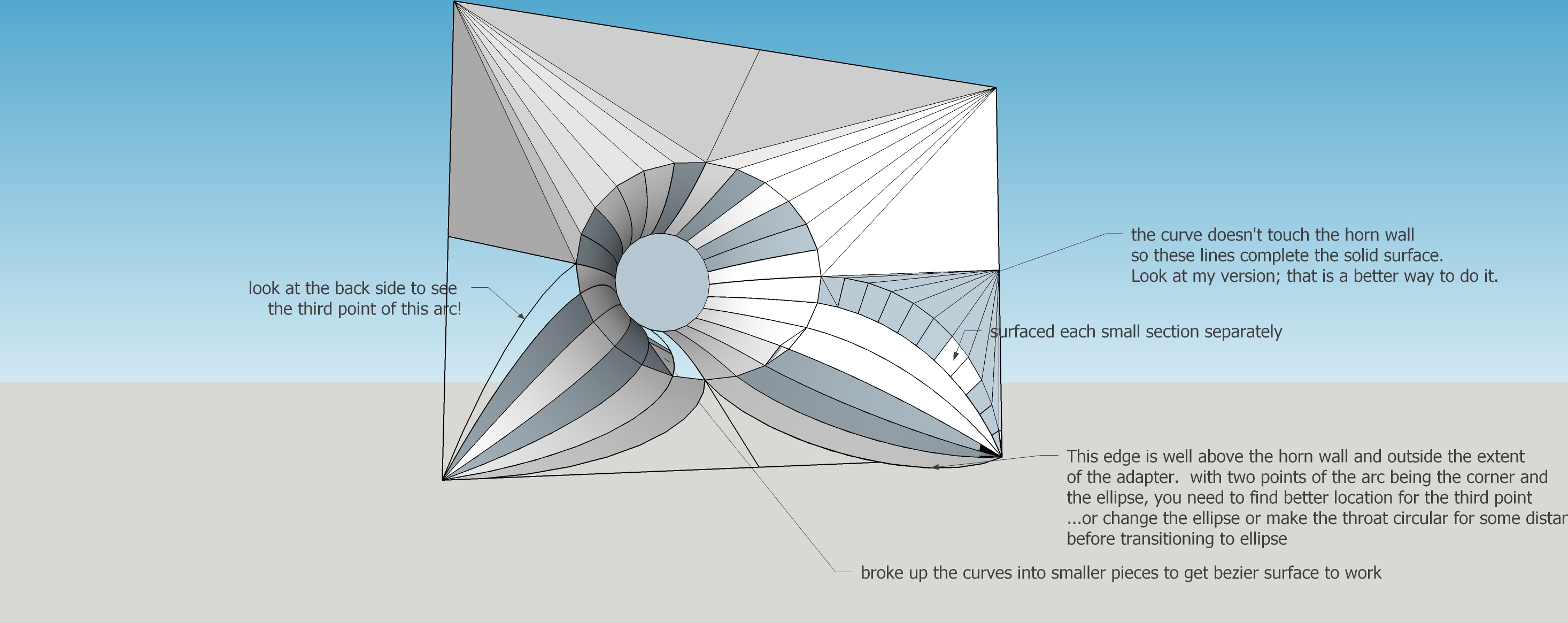
I can certainly see the curvature in your sketchup model. Your front to back arcs seem to start from the CD exit and go all the way to the corner. You have a circle at the CD exit and what appears to be an ellipse out where you start to transition to the rectangular cross section. I would have put a 2nd (expanded) circle about 6 mm in from the CD exit to force the throat to stay round that long and then started my arcs up into the corner from here. You have some issues with the longest arcs, those closest to the wall midpoints. Am I correct that your that the aspect ratio of your ellipse doesn't match the aspect ratio of the horn? Should it? I would try that to see if it worked better - had fewer issues at the edges of each quadrant.
The Draw Bezier Surface from curves works most but not all places. Sometimes you need to select ruled rectangle instead of ruled triangle. Sometimes you need to break up the curves into sections and then surface individual sections as I did in the lower right quadrant. If all else fails start drawing lines to create triangles.
I commented your drawing and am sending it back. I hope this gives you some ideas as to how to proceed. You need to do more of what I have been doing - trying different things to get better results.
This "hacking" and manual surface creation takes a lot of time. You can work on just one quadrant, make a group out of that quadrant, then cut and paste and rotate into the other 3 quadrants to save time.
I found errors in my axidriver model that was making me think the shorter curved sections were better. Disregard what I said about the length of the curved throat earlier.
I can certainly see the curvature in your sketchup model. Your front to back arcs seem to start from the CD exit and go all the way to the corner. You have a circle at the CD exit and what appears to be an ellipse out where you start to transition to the rectangular cross section. I would have put a 2nd (expanded) circle about 6 mm in from the CD exit to force the throat to stay round that long and then started my arcs up into the corner from here. You have some issues with the longest arcs, those closest to the wall midpoints. Am I correct that your that the aspect ratio of your ellipse doesn't match the aspect ratio of the horn? Should it? I would try that to see if it worked better - had fewer issues at the edges of each quadrant.
The Draw Bezier Surface from curves works most but not all places. Sometimes you need to select ruled rectangle instead of ruled triangle. Sometimes you need to break up the curves into sections and then surface individual sections as I did in the lower right quadrant. If all else fails start drawing lines to create triangles.
I commented your drawing and am sending it back. I hope this gives you some ideas as to how to proceed. You need to do more of what I have been doing - trying different things to get better results.
This "hacking" and manual surface creation takes a lot of time. You can work on just one quadrant, make a group out of that quadrant, then cut and paste and rotate into the other 3 quadrants to save time.
Attachments

Maybe rather than using Sketchit, Fusion360 might be a better (and also free) platform to do this with? It handles lofting (smoothly going from one shape to another) well and can even loft along 'guide' curves you can enter as a table of dimension values, such as OS, Tractrix, etc.
Ha! I remember your description of how you drew up your 3Dprinted horn included a few only partially deleted expletives.
For me, better the devil I know. I tried Fusion360 and it was just too different for me. I found a number of Sketchp extensions that reduce the pain associated with this kind of thing, including one that can draw an OS curve also. The learning curve on a new tool would be even more painful.
Likely different for MrOil. He may want to take your STL file and morph it into something that would work for him or find that it already works for him.
All this work on the mechanics of drawing a shape and I haven't even found/proven what shape is best yet. I do know the on-axis dip of an axisymmetric horn would kill me; I don't know if square is good enough or if I have to go to rectangular like everyone else (which sort of answers the question).
Syn horn with mid -ports
Hi there O: Most of the later post are about optimizing the horn geometry, hope you can arrange to optimize and construct the mid driver ports on the curved interior horn surfaces and the flat driver mounting pads on the out side. Sizing the pads, and placing them to optimize the port lengths may be challenging. ...regards, Michael
Hi there O: Most of the later post are about optimizing the horn geometry, hope you can arrange to optimize and construct the mid driver ports on the curved interior horn surfaces and the flat driver mounting pads on the out side. Sizing the pads, and placing them to optimize the port lengths may be challenging. ...regards, Michael
Found a lofting tool for Sketchup. It seems just what the doctor ordered for this problem
Organic modeling made simple with Curviloft | SketchUp Blog
I haven't tried it yet; still reading the tutorial. Even has ability to be guided by intermediate profiles and to respect tangency.
Organic modeling made simple with Curviloft | SketchUp Blog
I haven't tried it yet; still reading the tutorial. Even has ability to be guided by intermediate profiles and to respect tangency.
Found a lofting tool for Sketchup. It seems just what the doctor ordered for this problem
Organic modeling made simple with Curviloft | SketchUp Blog
I haven't tried it yet; still reading the tutorial. Even has ability to be guided by intermediate profiles and to respect tangency.
well half an hour to get through the installation help video then 1 minute to produce a trial loft.
What I need to do instead of lofting from a circle to a rectangle as I did for the trial, loft from the top of my round exit angle matched throat to the rectangular bottom of a 90x60 horn...and get it to respect tangency....but its already late here
Attachments

that looks pretty comparable to the F360 loft, and saves the trouble of learning a new tool. I had similar grief trying Sketchup after using Fusion. Working in 3d is hard enough without every package going at it differently
Hi,
That tool is awesome, but as you said, the tangency is a problem. I tried almost every function, but could only get a 90° orientation to the end surfaces...
I'll play around with it a bit...
@bwaslo Can you loft with respect to the tangency in fusion 360?
Thanks a lot!
That tool is awesome, but as you said, the tangency is a problem. I tried almost every function, but could only get a 90° orientation to the end surfaces...
I'll play around with it a bit...
@bwaslo Can you loft with respect to the tangency in fusion 360?
Thanks a lot!
- Status
- Not open for further replies.
- Home
- Loudspeakers
- Multi-Way
- 2-way Unity Horn from 300Hz (some noob questions)