I've been out of the diy audio hobby for a bit now. I've been focused on a small business I started. I'm currently restarting work on a 16nsb + 1 ring radiator corner line array, but alot has changed knowledge wise since I began the project. I have some thoughts and ideas of like to run by you guys relating to both CBT and corner line arrays.
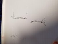
1) in some sense a true floor to ceiling line array comes close to approximating a sliver of a curve from a point source very far away, esp when you factor in floor and ceiling reflections. Is this true at all? Could something like the picture below bridge the gap between the two concepts? Basically you slightly curve the corner array and have angled ceiling and floor reflectors to make the reflections follow the curve. I have a crude picture below.
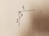
2) The next thought relates to doing a multi way corner line array. Getting the drivers as close to the corner as possible is optimal, but I'm guessing the lower you go, the further from the corner it can be without losing anything. Why not put the tweeter line way back in the corner, and have the lower end further out, at the same time creating directional control for the tweeter line?
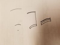
3) The third thought relates to CBT arrays. It seems like having two parallel rows is less than optimal since they aren't resting on the same sphere. Wouldn't it be better to have a separate thin tweeter row just in front of the woofer line. The curve of the tweeter line will be broader than the woofer line curve since it's further from the theoretical point source. With such incredible polar response coming from CBT arrays, as long as you factor in a delay, how far apart could the rows be?
4) array center to center spacing vs polar response of each driver. Has there been any research into how much a narrow vs wide polar response affects the necessary center to center spacing of drivers in an array? I'm guessing an array of laser straight polar responses requires closer c2c than a wide 180 degree polar response at all frequencies.
1) in some sense a true floor to ceiling line array comes close to approximating a sliver of a curve from a point source very far away, esp when you factor in floor and ceiling reflections. Is this true at all? Could something like the picture below bridge the gap between the two concepts? Basically you slightly curve the corner array and have angled ceiling and floor reflectors to make the reflections follow the curve. I have a crude picture below.
2) The next thought relates to doing a multi way corner line array. Getting the drivers as close to the corner as possible is optimal, but I'm guessing the lower you go, the further from the corner it can be without losing anything. Why not put the tweeter line way back in the corner, and have the lower end further out, at the same time creating directional control for the tweeter line?
3) The third thought relates to CBT arrays. It seems like having two parallel rows is less than optimal since they aren't resting on the same sphere. Wouldn't it be better to have a separate thin tweeter row just in front of the woofer line. The curve of the tweeter line will be broader than the woofer line curve since it's further from the theoretical point source. With such incredible polar response coming from CBT arrays, as long as you factor in a delay, how far apart could the rows be?
4) array center to center spacing vs polar response of each driver. Has there been any research into how much a narrow vs wide polar response affects the necessary center to center spacing of drivers in an array? I'm guessing an array of laser straight polar responses requires closer c2c than a wide 180 degree polar response at all frequencies.
Attachments
Last edited:
Looking at your first image, and presuming the ends are close to the floor and ceiling, there will be a reflection from these surfaces unless you end the line on them and normal to them. Ie, an array would work into free space but when you need a longer line, and this won't see that free space in a real listening room, you need to work with the surfaces. This means either using a curved line from the floor that ends in an open space part way up the room (or just a small line in the middle) or using a straight line from floor to ceiling.
Although this second option gives an infinite source distance, the room (which is a confined space, and an odd space wrt the expansion of sound) dictates the straight line, which shouldn't be shaded, and all expansion will be in the horizontal dimension.
Although this second option gives an infinite source distance, the room (which is a confined space, and an odd space wrt the expansion of sound) dictates the straight line, which shouldn't be shaded, and all expansion will be in the horizontal dimension.
The one thing you have going for you here is that you can waveguide high frequencies with a finite guide built into the other parts of the speaker in some creative way.2) The next thought relates to doing a multi way corner line array. Getting the drivers as close to the corner as possible is optimal, but I'm guessing the lower you go, the further from the corner it can be without losing anything. Why not put the tweeter line way back in the corner, and have the lower end further out, at the same time creating directional control for the tweeter line?
It isn't a perfect situation. Multi-way in a corner is (among other things) about allocating the free space vs utilising the surfaces, carefully.
It isn't possible to put un-folded waveguiding into a corner in a way that doesn't mess up the highest frequencies without either cutting into the wall to mount the drivers behind the corner, or building the HF guide to be self contained.
Looking at your first image, and presuming the ends are close to the floor and ceiling, there will be a reflection from these surfaces unless you end the line on them and normal to them. .
Right, that's by design to take advantage of some of the benefits of true floor to ceiling line arrays. With the curve and reflectors, at least the first reflection follows the shape of the theoretical curve.
Attachments
Last edited:
The one thing you have going for you here is that you can waveguide high frequencies with a finite guide built into the other parts of the speaker in some creative way.
It isn't a perfect situation. Multi-way in a corner is (among other things) about allocating the free space vs utilising the surfaces, carefully.
It isn't possible to put un-folded waveguiding into a corner in a way that doesn't mess up the highest frequencies without either cutting into the wall to mount the drivers behind the corner, or building the HF guide to be self contained.
I just had some time to read through some of the theory on how the synergy horns work, and it would seem like integrating the mids and highs that way would be beneficial. I'm pretty sold on the synergy concept at the moment, and I'm curious how well that could integrate into a floor to ceiling corner line array. Obviously it would involve building into the wall around the corner for a permanent install, but possibly a bulge in the throat for the mid and woofer columns wouldn't hurt fr too much.
For a traditional 3 way synergy, has anybody thought about using the b&g planar range? Their shape etc should make it easier to mount the mids close to the start of the throat vs normal drivers, plus they have very low distortion and high efficiency. In addition, the square shape of the neo3 seems perfect for a clean mount into the throat of a square wooden horn.
Last edited:
The floor and ceiling make the line behave like a larger one.. but only in one respect, and for this to work it requires the surface/s to cooperate so as not to lose this energy to a higher order mode. Since the room never deviates from constant floor and/or ceiling height there should be no call for vertical gradients or independent vertical travelling energy, but on the other hand any free end of a CBT calls for free space as that is the purpose of the shading.Right, that's by design to take advantage of some of the benefits of true floor to ceiling line arrays. With the curve and reflectors, at least the first reflection follows the shape of the theoretical curve.
I mainly like that concept from a artistic / architectural / marketing perspective. Imagine a sphere 18" sub in the corner, a small highly arched mid bass in front of it, a larger flatter midrange array in front of that, and finally a taller flatter tweeter line, maybe even spaced out a foot and not in a straight line.
It doesn't matter whether you modify the line with delay or level shading, it will cause a vertical gradient.
Personally, I prefer point source highs directed along, or away from the walls but filling the room if possible, and extending as low as possible. Not only is this easier with the highs but it begins not to matter with the lows, where lost energy is only of concern in keeping the response even.
Personally, I prefer point source highs directed along, or away from the walls but filling the room if possible, and extending as low as possible. Not only is this easier with the highs but it begins not to matter with the lows, where lost energy is only of concern in keeping the response even.
- Status
- This old topic is closed. If you want to reopen this topic, contact a moderator using the "Report Post" button.
- Home
- Loudspeakers
- Multi-Way
- CBT / corner line array thoughts