All I am saying is if you look for it, you will find that difference.
Well, I was not looking for it. I was expected to hear MTM is much better than single midrange, so I was confused. The reason we compared them is to see if more expensive MTM Amphion actually worth for the extra price. I have been using MTM for last 15 years, but more I know about speakers, more I'm confused.
Last edited:
I think the discussion so far hasn't taken into account the constraints originally imposed:
TPL150-H as tweeter XOed at 2 Khz and high enough efficiency for SET amps.
That tweeter is 9" high and with the 2 Khz XO makes usual CTC distance rules hard to achieve. The best one could do might be several 2.5"-3.5" drivers in rows across the top and bottom of the TPL as close to it as possible. Those horizontal short lines will each act as single drivers below 2 khz and generate sufficient efficiency. Matching their width to the TPL should match its horizontal directivity as well. It may look strange but it will work.
The small mid arrays will need help below a few hundred hz and those woofers can and should be spaced appropriately and crossed over to give some vertical directivity.
I think the discussion so far hasn't taken into account the constraints originally imposed:
TPL150-H as tweeter XOed at 2 Khz and high enough efficiency for SET amps.
That tweeter is 9" high and with the 2 Khz XO makes usual CTC distance rules hard to achieve. The best one could do might be several 2.5"-3.5" drivers in rows across the top and bottom of the TPL as close to it as possible. Those horizontal short lines will each act as single drivers below 2 khz and generate sufficient efficiency. Matching their width to the TPL should match its horizontal directivity as well. It may look strange but it will work.
The small mid arrays will need help below a few hundred hz and those woofers can and should be spaced appropriately and crossed over to give some vertical directivity.
How about a vertical line of 4" midranges to the side of the tweeter, a la Nola? Maybe a line of 4, 5 or 6 mids?
How about a vertical line of 4" midranges to the side of the tweeter, a la Nola? Maybe a line of 4, 5 or 6 mids?
The obvious disadvantage of mids side by side with the TPL is the lobing error that occurs when the listener moves off axis horizontally. If you only listen on axis that may be acceptable. But do you also only or mostly listen sitting down? Then you might be better off with a system design whose lobing errors are on the vertical axis.
Either way you will have to that issue because of the size of the TPL waveguide combined with your 2 khz XO point. Looking at the TPL data sheet, one would believe it could be crossed as low as 1 Khz but I have heard it sounds better crossed higher. Perhaps since you are not throwing much power at it you could crossover lower. Reducing XO to 1500 Hz would ease the system design. A steeper crossover slope might be part of the solution.
I suggested a short line of very small drivers above and below the TPL was twofold: minimize CTC and match horizontal directivity of the waveguide. Matching horizontal directivity is also be a consideration for a vertical line of mids next to the TPL. The line of mids would have good vertical directivity, which would mean little floor and ceiling bounce it its range but the power response would be compromised due to mismatch of directivity with the tweeter.
Let's say we have lines 4 2.5" drivers centered 1.5" above the edges of the TPL, per my original suggestion. That gives a CTC of 6". Per D'Appolito, this suggest a wavelength at XO of 9" or aXO frequency of 1500 Hz for a vertical lobe free design. The free tool XDIR tells me that with this spacing and 2000 hz XO, you still have that main lobe at ear height but also side lobes aimed at steep angles at floor and ceiling, at frequencies easily absorbed by carpeting.
To complete the system design, move up and down the baffle to a vertically symmetric pair of 8" or 10" drivers that are used up to 500 Hz or so. Look at KEF products for examples of this style of design, they use a coax (uniQ) driver at the center but the same principles apply
Stepped baffle to time-align the drivers? Making sure I'm not missing something, as my system is active and time-aligned through the digital xo and DSP, so wouldn't need to step the baffle for time-alignment, while I do need to manage diffraction and reflections of course.
-right, with dsp you won't need physical alignment.
 (..though you can benefit from a vertically "slant" baffle of a few degrees.)
Negative effects to horizontal polar response can be managed with a narrow line relative to freq.. with a fairly steep low-pass crossover. Effectively going "omni" but requiring a lot more gain due to boundry/baffle loss.
I'd probably move the Heil-type down to 1.5 kHz and use something like the 18 Sound 6ND410 in line of 4 or more drivers below 1.5 kHz to your mid-bass transition point. with the baffle width for the line being about the same width as the driver.
-right, with dsp you won't need physical alignment.
Indeed. Anything I can do to geometrically approach time-alignment will reduce the need for digital correction, which is always good practice.
Negative effects to horizontal polar response can be managed with a narrow line relative to freq.. with a fairly steep low-pass crossover. Effectively going "omni" but requiring a lot more gain due to boundry/baffle loss.
Yes, the plan is to take advantage of digital xo and make them steep - 8th order or so.
I'm not tracking the comment, though. If the tweeter with the horn has 80 degree horizontal dispersion, why are you recommending omni for the midrange? In my mind I want to meet the tweeter dispersion as much as possible in the xo region. But maybe I'm missing an important point and would appreciate if you could ellaborate on this.
I'd probably move the Heil-type down to 1.5 kHz and use something like the 18 Sound 6ND410 in line of 4 or more drivers below 1.5 kHz to your mid-bass transition point. with the baffle width for the line being about the same width as the driver.
It's funny I analyzed and ran some midrange horn prototypes and concluded I probably need to lower the xo point to about 1.6k if wanted to go that route. Then also looked into single direct radiators and concluded similarly. Maybe with arrays too?
In fact I looked into that driver for both horn and single direct radiator.The thing is this tweeter has a resonance at 1.8k and people who tried xo at 2kHz claim it's noticeable so I'm trying to get there.
However, what's driving your recommendation to lower the xo point? Are you thinking of an array in MTM configuration where each M represents 2 or 3 drivers? Hence lowering xo to that point would allow for center to center spacing under one wavelength between the two drivers closest to the tweeter.
Or do you envision a line of 4 or more above/below the tweeter, or to the side of the tweeter?
Thanks for the insights!
Either way you will have to that issue because of the size of the TPL waveguide combined with your 2 khz XO point. Looking at the TPL data sheet, one would believe it could be crossed as low as 1 Khz but I have heard it sounds better crossed higher. Perhaps since you are not throwing much power at it you could crossover lower. Reducing XO to 1500 Hz would ease the system design. A steeper crossover slope might be part of the solution.
I listen mostly sitting down, at about 7.5 feet from the tweeter.
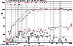
Indeed the tweeter can be xo lower and some do. Vapor Audio 2-way Arcus uses this tweeter xo at 1.1kHz to a 10" AE woofer. Yet, as you heard, there is a resonance at 1.8k I'm trying to avoid - if possible.
I suggested a short line of very small drivers above and below the TPL was twofold: minimize CTC and match horizontal directivity of the waveguide. Matching horizontal directivity is also be a consideration for a vertical line of mids next to the TPL. The line of mids would have good vertical directivity, which would mean little floor and ceiling bounce it its range but the power response would be compromised due to mismatch of directivity with the tweeter.
Let's say we have lines 4 2.5" drivers centered 1.5" above the edges of the TPL, per my original suggestion. That gives a CTC of 6". Per D'Appolito, this suggest a wavelength at XO of 9" or aXO frequency of 1500 Hz for a vertical lobe free design. The free tool XDIR tells me that with this spacing and 2000 hz XO, you still have that main lobe at ear height but also side lobes aimed at steep angles at floor and ceiling, at frequencies easily absorbed by carpeting.
Thanks for the explanation. On xDir you model as MTM because each M represents a horizontal line of midranges, right? And you use 0 phase? And this models vertical lobbing.
Is there a way to use xDir to model MTM where each M represents a vertical array of 2 or 3 drivers?
Frankly I struggle with the idea of maybe six 2.5" midranges going down to 500Hz and meeting two 10" midbasses there and sounding correct. Six 2.5" have 20% or the area of two 10" vs six 4" having 50% and four 6" having 70%. Seems like little midrange surface, doesn't it?
To complete the system design, move up and down the baffle to a vertically symmetric pair of 8" or 10" drivers that are used up to 500 Hz or so. Look at KEF products for examples of this style of design, they use a coax (uniQ) driver at the center but the same principles apply
Thanks for the tip! I was planning two 10" per side from 80 to about 450Hz. I guess I'll have to revising to four 10"
Thanks for the explanation. On xDir you model as MTM because each M represents a horizontal line of midranges, right? And you use 0 phase? And this models vertical lobbing.
Is there a way to use xDir to model MTM where each M represents a vertical array of 2 or 3 drivers?
Frankly I struggle with the idea of maybe six 2.5" midranges going down to 500Hz and meeting two 10" midbasses there and sounding correct. Six 2.5" have 20% or the area of two 10" vs six 4" having 50% and four 6" having 70%. Seems like little midrange surface, doesn't it?
Thanks for the tip! I was planning two 10" per side from 80 to about 450Hz. I guess I'll have to revising to four 10"
Yes, I model as MTM and with 0 degrees. XDIR apparently just models point sources. The results for actual drivers are approximate but probably reasonable where the wavelength is long compared to the effective driver diameter in the vertical direction - which will be much greater for a vertical line of drivers. I think you can move up to EDGE which allows you to model the driver shape - where the line wodel be modelled as a skinny rectangle.
As to relative surface areas between mids and woofers - one of the main considerations is enough surface area to keep excursion of the drivers within the linear region. By that criterion, drivers covering 500-2000 Hz need less surface area*excursion than those covering 80 to 500 Hz. The other way driver surface area matters is in how it affects directionality and center to center distance - where 2.5" is a solution, not a problem.
Of course you need to find appropriate 2.5" drivers. I have some familiarity with 3FE25. I know there was a Synergy done with a 2.5" full range driver used as tweeter down below 500 Hz but I don't recall the part number.
After smooth on axis frequency response, I think sounding right will depend on the crossovers, the directivity matches at XO, and the room. The MTM, vertically symmetric designs give vertical directivity which limits hard to treat floor and ceiling bounce, helping tame the room. A vertical line of mids may not give you a good enough directivity match and its hard to know in advance how that will affect the sound. The same could be said, I suppose, for my or any proposal. I've also seen builds using the TLP150H where the center to center criterion has been ignored. One of the best uses for XDIR would be evaluating how large a CTC you can get away with and this might rationalize using larger mids than 2.5" or 3".
As to the number of 10" woofers, I didn't meant to imply that you needed four. Two should be sufficient to get to 80 Hz.
I'm not tracking the comment, though. If the tweeter with the horn has 80 degree horizontal dispersion, why are you recommending omni for the midrange? In my mind I want to meet the tweeter dispersion as much as possible in the xo region. But maybe I'm missing an important point and would appreciate if you could ellaborate on this.
It's funny I analyzed and ran some midrange horn prototypes and concluded I probably need to lower the xo point to about 1.6k if wanted to go that route. Then also looked into single direct radiators and concluded similarly. Maybe with arrays too?
The thing is this tweeter has a resonance at 1.8k and people who tried xo at 2kHz claim it's noticeable so I'm trying to get there.
However, what's driving your recommendation to lower the xo point? Are you thinking of an array in MTM configuration where each M represents 2 or 3 drivers? Hence lowering xo to that point would allow for center to center spacing under one wavelength between the two drivers closest to the tweeter.
Or do you envision a line of 4 or more above/below the tweeter, or to the side of the tweeter?
Thanks for the insights!
(Just suggestions.)
-Get rid of the Horn. With the steep crossover it's not doing much that's genuinely helpful, and it's generating additional diffraction. The objectionable resonance may well be an artifact of the horn.
The digital crossover allows you corrections in spl (without much power loss for modest gain over a very limited bandwidth).The lower crossover point helps with the tweeter's radiation and net clarity for the loudspeaker while limiting the midrange's problems with directivity at the top of its pass-band.
Top to bottom: MMMMTWW, or MMMMMMTWW.
The 18Sound 6ND410 because it's efficient into the lower mid (300 Hz is 96 db) with it's higher Qts. In combination with the array it should provide enough gain so that you aren't wasting power even with the substantial loss of baffle area.
Frequency Response - drivervault
Tweeter about 28-30 inches off of the floor (bottom of driver) aimed upward with about a 10 degree vertical tilt (..backward). (..in fact, all the baffle should have a 10 degree vertical tilt.)
Perhaps the 12PR300 16 ohm x2 in parallel on each side of the cabinet at the bottom near the floor to avoid most floor-bounce.
Ex.
Baffle shape: largely rounded and tapered from bottom to top (12" at bottom and 7" at top).
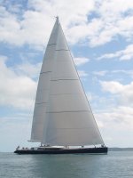
Overall look would likely be like a sail from the side with only the mid-bass woofers visible at the bottom on each side. (note: from picture that the "rear" of the first (fore) sail would be the front baffle and the front of the sail would be the rear of the loudspeaker.)
Attachments
I wouldnot use tpl with out horn.
It is type of driver you better at least try to match directivity with out horn it was 120deg driver on normal standing position.
Many people had said it and im saying again.
Tpl is so clean that you have to use midrange that match sounding nearly as same as tpl cause when crossover has happened and sound is coming from tpl you locate that sound is coming from tpl.
For me its somewhat dissapointing this melting in not to happened, i might be too demanding for my system.
Best situation with tpl has been 5000hz crossing steep xo, 3m distance and i still locate tpl.
Worst has been from 6meters midrange 90deg and tpl with out horn 120deg directivity mismatch.
Good journey to find that midrange, my tpl are in my garage waiting for that buddy.
After smooth on axis frequency response, I think sounding right will depend on the crossovers, the directivity matches at XO, and the room. The MTM, vertically symmetric designs give vertical directivity which limits hard to treat floor and ceiling bounce, helping tame the room. A vertical line of mids may not give you a good enough directivity match and its hard to know in advance how that will affect the sound. The same could be said, I suppose, for my or any proposal. I've also seen builds using the TLP150H where the center to center criterion has been ignored. One of the best uses for XDIR would be evaluating how large a CTC you can get away with and this might rationalize using larger mids than 2.5" or 3".
Thanks for the continued help!
I did some quick drawings to picture some alternatives. Used PowerPoint as I don't have ACad anymore. Good enough at this stage. Please ignore the midbasses for now. I placed the TPL at ear-level, for the time being with horn included - especially if I'm to lower the xo to around 1.5k I definitely want the horn I think.
The left drawing uses 3FE25. Is this the configuration you envision? So side-to-side drivers to shape horizontal directivity, and same for vertical?
For all options I could use more drivers, but especially for 4FE35 and 6ND410 I would space them closer together as total height would soon become a constraint.
I imagine the 4" and 6" options would provide good vertical dispersion, right?
For horizontal dispersion I don't have polar plots for these, but can approximate using: dispersion= 1,000,000/(effective diameter x frequency)
So for the 4" 4FE35 I estimate 3.5" effective diameter, and then dispersion @ 2kHz would be 142 degrees...a mismatch with the 80 degree horizontal dispersion of the TPL150H. Here it would make sense to use the TPL without the horn. Correct?
For the 6" 6ND410 I estimate 5.25" effective diameter, and then dispersion @ 2kHz would be 95 degrees which I guess is close enough to 80 from the TPL with horn. If I were to drop the xo point, however, at 1.5kHz dispersion would be 126 degrees so a mismatch with the horn again.
Then I also need to run xDir to look into c-t-c lobbing effects. I struggle with the underlying assumption in xDir that midranges are point sources, even the tweeter where my tweeter is not a point source and the midrange arrays wouldn't be point sources either, hence not sure the result of these simulations are valid. The midrange array presents itself as a line source rather than a point source, so MTM effects might be a lot different.For the 6" 6ND410 I estimate 5.25" effective diameter, and then dispersion @ 2kHz would be 95 degrees which I guess is close enough to 80 from the TPL with horn. If I were to drop the xo point, however, at 1.5kHz dispersion would be 126 degrees so a mismatch with the horn again.
BTW, I have also seen MTM with the TPL150H where the c-t-c criteria seems to have been ignored. Others I saw saying the effect is not as perceivable as simulations lead us to believe. Dieter Achenbach in Germany, who owns a speaker parts showp and could use any driver he wants, uses MTM with TPL-150H and two PHL 8" for midrange, and then woofers for the bass. Go figure
Attachments
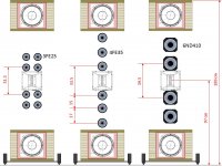
I think you've got the general idea - stacking drivers horizontally in attempt to match horizontal directivity, offsetting additional drivers vertically to control vertical directivity in MTM fashion.
I wouldn't put four 3" drivers stacked 2H x2V because that puts their center where the center of an 8" driver would be. I would go three across instead to get the center closer. The same considerations apply to your two left hand drawings - the acoustic center of each pair of vertically stacked mids is more distant than would be that of a single 8" driver and the 8" driver would be a better, even good match horizontally.
As you note, its hard to get a direct radiator to match a waveguide. It really can only be done approximately and only where the waveguide is starting to or has lost control and the direct radiators are starting to beam, another argument for lowering the XO frequency, to about 1.3 khz from what I see on the TPL spec sheet. And the results with XDIR are as approximate as they are quick; accurate simulation results require a lot more work in tools (Akabak, ABEC) that can have long learning curves!
It seems there is no perfect solution. What then is the least evil?
Consider MTM with 8" mids: XDIR shows manageable lobes below about 1300 Hz. Much above that and the floor and ceiling lobes start to dominate and the central beam narrows. Just a little bit above a 1.3 Khz XO, you would have the directivity of the waveguide. With steep XO filters, just a little bit below you have the directivity of the pair of mids, which is more or less omni with about 2 db greater on vertical axis.
I know that the small drivers (3FE25 and 4FE35) don't have credibility with you. My own experience argues to the contrary. I used 4 4FE35's per side in Synergy corner horns initially down to 200 Hz but ultimately raised to 300 Hz for directivity reasons - crossing to a bass bin at 300 Hz reduced floor bounce. Yes, this was corner loaded but my design target at Xmax was 120 db sound power on HornResp. The low end of their range is below where there is any benefit from horn loading.
Using them or better the 3FE25's instead of 8" drivers gives you a much stronger forward lobe and correspondingly weaker and narrower floor and ceiling lobes (to the extent that we can believe XDIR) a 1300 Hz XO, where it needs to be - the point where the waveguide loses control. I think this is worthwhile. If you can't see using the small mids all the way down to 500 Hz then crossover to the 10" woofers at a higher frequency. The concept of using a small mid over a limited frequency range as a bridge between woofer and tweeter is well proven. If those are true pro woofers, as opposed to subwoofers, they will handle up above 1 Khz; the small mids are needed almost soley because of CTC.
(Just suggestions.)
-Get rid of the Horn. With the steep crossover it's not doing much that's genuinely helpful, and it's generating additional diffraction. The objectionable resonance may well be an artifact of the horn.
Unfortunately the resonance is from the driver; not the horn. But maybe is not that bad a concession after all.
Top to bottom: MMMMTWW, or MMMMMMTWW.
Tweeter about 28-30 inches off of the floor (bottom of driver) aimed upward with about a 10 degree vertical tilt (..backward). (..in fact, all the baffle should have a 10 degree vertical tilt.)
Wondering about the tilt combined with such long array. The bottom driver would be much closer to my ears than the top one. Wouldn't that sound diffuse?
Thanks for the link to the measurements! Nice driver.
"Each Beyma TPL150, which leaves our house, undergoes a modification, which eliminates a small weak point and makes the frequency response in the critical range by 4 kHz"
from achenbach
interesting
Interesting. I wasn't aware of this. He has probably figured out how to reduce that resonance. But my point about his Son XL speaker was pointed to his use of MTM with TPL150H and two 8", so kind of ignoring c-t-c "common wisdom". And having good reviews.
Unfortunately the resonance is from the driver; not the horn. But maybe is not that bad a concession after all.
Wondering about the tilt combined with such long array. The bottom driver would be much closer to my ears than the top one. Wouldn't that sound diffuse?
Thanks for the link to the measurements! Nice driver.
The resonance isn't showing up as a resonance. You'd see something like that in several respects, and I'm not seeing it. (..though there might be a quality control problem among drivers.) CSD looks clean as well:
http://www.lightsoundjournal.com/images/2008/tpl4.jpg
The "tilt" is there for getting good vertical dispersion out of a design like this over a range of listening distances from the loudspeaker. Basically lower the tweeter height and "aim" up to the length of the line. At your position the line is a point source and at 1.5 kHz cut-off and because of the "tilt" there is added pressure loss higher in freq.s - all of which makes it a moot point.
Note: all of this is pretty easy to try for yourself with dsp. I would recommend trying all of these basic designs with some cheap drivers for your line and an inexpensive solid-state amp(s). (..and some cheap plywood or even cardboard.) It should give you a good idea where you'll want to head with your final design. (..if you hear a tweeter resonance, where you like your line low-passed, etc..) BTW, with my array experiments I did like the back-ward tilt on almost *all* designs (..including a full array line).
-it's Brandon's (Augerpro's) website (..very nicely providing the data to others).
Last edited:
Interesting. I wasn't aware of this. He has probably figured out how to reduce that resonance. But my point about his Son XL speaker was pointed to his use of MTM with TPL150H and two 8", so kind of ignoring c-t-c "common wisdom". And having good reviews.
Yeah, i believe 8" or even 10" could be soundwise match.
Could be just xo tweak to that tpl
I think you've got the general idea - stacking drivers horizontally in attempt to match horizontal directivity, offsetting additional drivers vertically to control vertical directivity in MTM fashion.
How do I run the math for beam width of two woofers side by side running the same frequencies?
I wouldn't put four 3" drivers stacked 2H x2V because that puts their center where the center of an 8" driver would be.
Good point! Thanks
Consider MTM with 8" mids
Definitely an option. B&C 8PE21.
I know that the small drivers (3FE25 and 4FE35) don't have credibility with you.
The concept of using a small mid over a limited frequency range as a bridge between woofer and tweeter is well proven. If those are true pro woofers, as opposed to subwoofers, they will handle up above 1 Khz; the small mids are needed almost soley because of CTC.
You would be surprised. 4FE35 has very nice extension: flat 300 to 5500Hz. Nice. Sensitivity at 91dB is a little low for my needs, and the dispersion pattern of such a small woofer is of concern. That is why I asked about the math to understand beam width side by side.
Midbass: Beyma 10G40. Can easily go up to 1kHz, but not their strength of course.
- Status
- This old topic is closed. If you want to reopen this topic, contact a moderator using the "Report Post" button.
- Home
- Loudspeakers
- Multi-Way
- Array for midrange: good idea?