Hey everyone, I have been planning a 3 way speaker with the woofer housed in a T-Line. I have not seen any speakers of this configuration which leads me to believe I might be missing something as to why this might be a bad idea. I need the help of people more knowledgeable then myself to perhaps steer me straight if need be. 
Drives are;
Woofer Seas Prestige 8" Woofer CD22RN4X H1192 Crossed at ?
Midrange ? Don't know yet looking for a 4" or 5" max. To be crossed over at 3K
Tweeter Tang Band RT-2202S Aluminum Ribbon Tweeter Matched Pair 6 Ohm To be crossed at 3K 3rd order
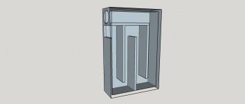
Enclosure Tweeter, and Mid get there own sealed enclosure and woofer gets the T-Line. I was thinking on making the port 14' long for a 1/4 tunning of 20HZ I know this will be massive. I was thinking on something like this
Drives are;
Woofer Seas Prestige 8" Woofer CD22RN4X H1192 Crossed at ?
Midrange ? Don't know yet looking for a 4" or 5" max. To be crossed over at 3K
Tweeter Tang Band RT-2202S Aluminum Ribbon Tweeter Matched Pair 6 Ohm To be crossed at 3K 3rd order
Enclosure Tweeter, and Mid get there own sealed enclosure and woofer gets the T-Line. I was thinking on making the port 14' long for a 1/4 tunning of 20HZ I know this will be massive. I was thinking on something like this
Attachments
That's not modelling software, that's graphics software. Dave is referring to software that accurately models the acoustic behaviour.
By offset driver he means moving the driver centre x distance along the line from the throat (sealed end) in order to suppress activiation of some of the undesirable pipe harmonic modes. End-loading a driver provides maximum excitation to the line fundamental and all odd order harmonics (untapered QW pipes only have odd order). By moving it along the line you can attenuate some of these unwanted harmonic modes, reducing the need for stuffing.
Line tuning is a function of acoustical length (i.e. physical length and taper), rather than phyical axial length alone. Gain is a function of bulk. Both are (or should be) determined by the driver requirements / characteristics; TLs & their variations are like any other vented enclosure insofar as driver & enclosure are a system rather than existing separately from each other -you can't just stuff a driver into a pipe of random length & expect good results; unfortunately, it doesn't work that way. Would that it did, life would be a lot simpler.
As noted, there have been many 3-way transmission line / QW variations since the 1930s. Bailey's for example was a 3-way, as were many of its acoustical labyrinth predecessors. Then there were classic Radfords, IMFs, TDLs, HFN / Rogers, Fried, IPL, PMC, Ferrograph etc. products to name a few, not including the DIY designs over the decades.
Last edited:
Oh, I understand. No I did not use a software. Please excuse my arrogance. The more I learn the more I realize just how little I actually know. I now have found some speakers that were multi-way T-Lines. Just had not looked hard enough.
With moving the driver along the line is that what BOSE did in the Acoustimass (same principle?)

I was using the classical idea from Classic TL Design -- Jon Risch, I had not thought of distortion except for the fact that I figuared folds in the line would help lower distortion. I have also just realized that the enclosure does not behave like a bass reflex and 20hz 1/4 wave line is far to low. I also though that using a far amount of stuffing throughout the line would help with mid frequency peaks, as well as leaving the last portion (few feet from the exit of the port) unstuffed and tuning that portion with REW and my minidsp mic with adding different density's till I got a fairly flat frequency response in my semi anechoic backyard
With moving the driver along the line is that what BOSE did in the Acoustimass (same principle?)
I was using the classical idea from Classic TL Design -- Jon Risch, I had not thought of distortion except for the fact that I figuared folds in the line would help lower distortion. I have also just realized that the enclosure does not behave like a bass reflex and 20hz 1/4 wave line is far to low. I also though that using a far amount of stuffing throughout the line would help with mid frequency peaks, as well as leaving the last portion (few feet from the exit of the port) unstuffed and tuning that portion with REW and my minidsp mic with adding different density's till I got a fairly flat frequency response in my semi anechoic backyard
Last edited:
Bose does all sorts of strange things, some of them make sense, some are more marketing or pyscho-acoustics. I would not look to them for guidance unless you really know what you are doing so that you can separate the interesting stuff from the chaff.
The Risch article is on one of my community sites and is really there only as a historical reference. Before 1999 when Martin & Augspurger released sw that properly simulates a TL it was the technique typically used to do a TL. The modeling sw does a WAY better job and gives you a much larger space to work in. Whereas with classic methods you were rarely likely to design an optimum line, with the sw you could be pretty sure that what you built was really similar to what you modeled. The modelers also brought an understanding of the affect of taper, the benefits of offset drivers, and the concept of a restricted terminus (ie ML-TLs).
dave
A long line with a constant area is going to have lots and lots of dips and peaks in its response. Using an offset driver location will smooth those dips and peaks some, but not as much as would be optimal. Stuffing helps, too, but to adequately smooth the response with stuffing will be severely detrimental to the bass response. A tapered line will be much better. Your choice of the Seas woofer listed in your first post is not a good choice for any kind of TL, except for possibly and ML-TQWT, due to its very low Qts of 0.24. The optimum tuning frequency for it will be significantly higher than its 20-Hz fs.
Paul
Paul
Oh, I understand. No I did not use a software. Please excuse my arrogance. The more I learn the more I realize just how little I actually know. I now have found some speakers that were multi-way T-Lines. Just had not looked hard enough.
With moving the driver along the line is that what BOSE did in the Acoustimass (same principle?)
I was using the classical idea from Classic TL Design -- Jon Risch, I had not thought of distortion except for the fact that I figuared folds in the line would help lower distortion. I have also just realized that the enclosure does not behave like a bass reflex and 20hz 1/4 wave line is far to low. I also though that using a far amount of stuffing throughout the line would help with mid frequency peaks, as well as leaving the last portion (few feet from the exit of the port) unstuffed and tuning that portion with REW and my minidsp mic with adding different density's till I got a fairly flat frequency response in my semi anechoic backyard
Okay good to know. So QTS is a factor in deciding a good driver, if so why and what would be the recommended range. And are there any other factors to consider in choosing a driver that I have missed? Would it be correct in assuming that a higher turned box will yield less issues in turms of peaks and dips because of the shorter line length?
Thanks to all for the help.
Thanks to all for the help.
Would it be correct in assuming that a higher turned box will yield less issues in turms of peaks and dips because of the shorter line length?
No. You will still have the same train of harmonics, but being higher in frequency they are easier to deal with.
dave
So QTS is a factor in deciding a good driver, if so why and what would be the recommended range. And are there any other factors to consider in choosing a driver that I have missed?
Depends on who you ask, but using reflex, horn theory as a guide, < ~0.312 = inverse tapered TQWT, ~0.312 - 0.52 = constant tapered TL, ~0.52 - 0.673 = positive tapered TQWT [horn] and ~0.673 - up design per Fs/Qts' [aka Alpha TL alignment].
That said, a ~0.403 yields a max flat alignment [Fb[p] = Fs], so normally the goal around here and suggest you use MJK's CLassic TL Alignment tables to do your design: Quarter Wavelength Loudspeaker Design
http://www.quarter-wave.com/TLs/Alignment_Tables.pdf
http://www.quarter-wave.com/TLs/Alignment_Tables_Calculator_3_3_09.xls
Well, the TQWTs are 1/2 WL resonators, so with both even and odd harmonics are inherently smoother than the TL's odd only harmonics.
All that said, TLs are best suited for either getting an IB response in a much smaller cab or for use over a narrow BW such as a woofer; for the rest, mass loaded [vented] variants are much preferred since they are smaller, smoother over a wide BW at a higher acoustic efficiency due to much less damping required.
GM
What do you mean by "constant tapered TL"? Based on your other TL descriptors in that sentence, I think you mean a non-tapered TL with a constant area. From my experience, I prefer drivers with a Qts of 0.35 to ~0.50, with both tapered (decreasing area) and mass-loaded TLs very likely to model and perform quite well, with drivers located at either the 1/5 or 1/3 points.
Paul
Paul
Depends on who you ask, but using reflex, horn theory as a guide, < ~0.312 = inverse tapered TQWT, ~0.312 - 0.52 = constant tapered TL, ~0.52 - 0.673 = positive tapered TQWT [horn] and ~0.673 - up design per Fs/Qts' [aka Alpha TL alignment].
That said, a ~0.403 yields a max flat alignment [Fb[p] = Fs], so normally the goal around here and suggest you use MJK's CLassic TL Alignment tables to do your design: Quarter Wavelength Loudspeaker Design
http://www.quarter-wave.com/TLs/Alignment_Tables.pdf
http://www.quarter-wave.com/TLs/Alignment_Tables_Calculator_3_3_09.xls
Well, the TQWTs are 1/2 WL resonators, so with both even and odd harmonics are inherently smoother than the TL's odd only harmonics.
All that said, TLs are best suited for either getting an IB response in a much smaller cab or for use over a narrow BW such as a woofer; for the rest, mass loaded [vented] variants are much preferred since they are smaller, smoother over a wide BW at a higher acoustic efficiency due to much less damping required.
GM
A little update, I am doing research into more of how T-Lines are constructed, I see that its very easy to make a T-Line but very difficult to make a good one and very hard to make a great one. I also see that post's I have read on the SMD forum are very misleading and really have no relevance to modeling an accurate design. I am however finding different theories that contradict others who seem to be authority's on the matter.
(Please do not take this the wrong way everyone) My question is for all is, are T-Line's more theory based on facts? Are there definite authority's on the matter. I really like Martin J. King He seems credible and I have asked to join his Yahoo group with the hope of being accepted of course.
Can I also get some recommendations for modeling software. I have attempted to get Martin J. King MathCAD but it requires a username and password. I'm guessing I have to join the group and ask maybe? I have also found the software SoundEasy to have T-Line ability. What I use now is BassBox Pro. and it does not.
Martin King is one of the most expert in TLs. His software is the example by which others are judged. George Augspurger released his TL software at the same time as Martin (1999). It was based on a different paradigm but yielded essentially the same results. Martin has continuously improved his model, George has not, but his original papers are well worth a read.
Leonard software has a good TL modeler but seemed to have gone MIA. HornResp will also model TLs and they have recently added damping to their model. Bob Brines, Scott Lindren, Paul Kittinger, Greg Monfret, and even myself know TLs pretty well (i let Scott actually design any i use, and i do proper drawings of all Scott’s designs)
dave
What do you mean by "constant tapered TL"? Based on your other TL descriptors in that sentence, I think you mean a non-tapered TL with a constant area. From my experience, I prefer drivers with a Qts of 0.35 to ~0.50, with both tapered (decreasing area) and mass-loaded TLs very likely to model and perform quite well, with drivers located at either the 1/5 or 1/3 points.
Paul
Yes, 'constant' as in it has a constant cross sectional area [CSA] along its length.
Not surprised, in the designs I've seen, you prefer ~3x the stuffing density I prefer, so a lot more alignment flexibility.
GM
HornResp will also model TLs and they have recently added damping to their model.
They ???
- Status
- This old topic is closed. If you want to reopen this topic, contact a moderator using the "Report Post" button.
- Home
- Loudspeakers
- Multi-Way
- 3-Way In T-Line Need Conformation I'm not Mad