Hello, this is my first post and I'm very new to the world of HiFi so go easy! I've posted in AVforums but I need technical advice so I thought I'd try here.
I recently bought some KEF Q70 floor standing speakers from a car boot sale for £20. I thought I'd got a bargain but it was not to be as I've since found out they aren't working properly. Gutting as the guy I bought them off assured me they worked 'fine'. Why don't people just tell the truth?! Anyway...
I connected them bi-wire to my Denon AVR and it seems I have the following problems:
Mid range not working on one, and mid range and low frequency not working on the other one (although both LF woofers do work when connected directly.
I've had a look at the crossover and can see a couple of resistors and an inductor that appears to have blown. This means a dismantling job and rebuilding the crossovers is on the cards. But I've never done this before.
I have the wiring diagram from KEF and can see which bits I need. The problem is, I can't kind exact specification replacements from Farnell.
Has anyone rebuilt KEF crossovers here? Is it OK to use components that are close but not the same specs?
I'll post the bits I need later, with the closest I've found on Farnell and see what opinions are, or am I wasting my time trying to repair them?
I've never bought a pair of speakers second-hand that didn't have something wrong with them! I suppose that is why people sell or give them to charity shops.
But most old speakers are worth it just for the cabinets. 😎
This one looks quite challenging to fix, with 160mm (polycone?) drivers, including a full range Uni-Q driver up top.
Crossover shouldn't be hard to fix. Those look like 50-100V non-polar electrolytics, available from Falcon Acoustics and Wilmslow Audio. Get within 10% on tolerance, and you'll be OK.
Sandcast or wirewound resistors of 3, 7 and 10W rating are industry standard.
Coils rarely fail, and are tough as old boots. You'll need a new 40W soldering iron and some non-toxic unleaded solder and some long nose pliers and some wirecutters. Soldering irons from Maplin often come with a solder-sucker thrown in. You certainly want to work quickly with capacitors, say in and out within 5 seconds and blow on them to cool things down, or start again. Resistors are quite rugged, as are coils.
After all that, if the drivers are damaged, we are looking at getting ingenious to keep the budget down. It would be expensive to replace the Uni-Q driver. But the cheapskate might add a tweeter to the top of the cabinet and look at some peerless units like the Peerless 830874.
Be interested in seeing the actual schematic and knowing if these are 4 or 8 ohm drivers, which you can establish with a DC resistance measurement on a £5 meter. You'll need to look up 4 band resistor colour codes to identify that 1-2W little resistor. Looks like a prime candidate to fry!
Attachments


Last edited:
You'll be running into waiting for moderation for the next 4 posts, IIRC.
BTW, it is very easy to test individual drivers just by connecting a 1.5V battery across the terminals. They should move and crackle! Or do a resistance reading across the terminals, looking for 3-6R.
Sounds like the basses might have some life in them. It's unusual for a coil to fail, and it might just be a dry joint in the soldering or other break somewhere.
A bass circuit is usually just a series coil and a capacitor shunt to earth, so a continuity test is easy enough. Most coils should measure 0.2-1R resistance.
Old wet NP electrolytics do dry out over many years, and degrade. I'm hoping that is all that is wrong with my current restore project, an ancient Monitor Audio MA7, which has a weak but working tweeter on one channel.
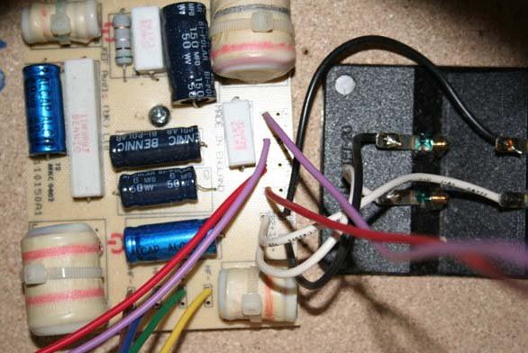
So a bit of an update. I took both speakers apart and got photos of the crossovers and it isn't a pretty sight!
This is the first crossover in which the only thing working is the tweeter. No mid range, and neither LF woofer are working (although both work when driven directly):

This is the crossover of the other speaker. The tweeter AND the LF woofers are working on this, but not mid range at all. This one looks much worse than the other one though which is surprising as the LF is working on this one.

So I'm guessing from looking at these it's gonna be a case of removing and replacing all the resistors, inductors and capacitors?
This is the first crossover in which the only thing working is the tweeter. No mid range, and neither LF woofer are working (although both work when driven directly):
This is the crossover of the other speaker. The tweeter AND the LF woofers are working on this, but not mid range at all. This one looks much worse than the other one though which is surprising as the LF is working on this one.
So I'm guessing from looking at these it's gonna be a case of removing and replacing all the resistors, inductors and capacitors?
I'm guessing from looking at these it's gonna be a case of removing and replacing
all the resistors, inductors and capacitors?
Probably not. It's well worth it to buy an inexpensive voltmeter to test the resistances and inductors,
since most will be probably ok. If the meter can test capacitors, that's even better.
DT-9025A Digital Multimeter AC/DC Ammeter Resistance Capacitance Tester with LCD Display-TVC-Mall.com
Digital DT-9205A Multimeter LCD AC/DC Ammeter Resistance Capacitance Tester
Last edited:
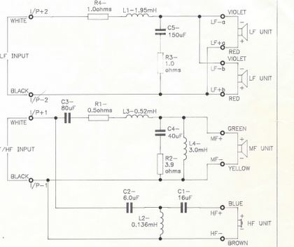
And here is the wiring diagram from KEF themselves...
If possible I'll need some advice on what bits to get to replace. I looked on Farnell today, and struggled to find parts with the same specifications, and I have no idea what I would be able to get away with tolerance wise.
If possible I'll need some advice on what bits to get to replace. I looked on Farnell today, and struggled to find parts with the same specifications, and I have no idea what I would be able to get away with tolerance wise.
An externally hosted image should be here but it was not working when we last tested it.
Also, can anyone recommend a good HiFi repair shop near Peterborough UK. I'm thinking it might be safer to take it to somewhere who won't break it, or make the problems worse.
Dylan, this is DIYaudio. We don't DO repair shops! 😀
I have been battling mightily with the notorious photobucket to get the images, which are invisible so far... 😱
Some progress. This is a pristine crossover:
I am already quite exhausted. But the pieces of the puzzle are in place. 😎
I have been battling mightily with the notorious photobucket to get the images, which are invisible so far... 😱
Some progress. This is a pristine crossover:
This is the first crossover in which the only thing working is the tweeter. No mid range, and neither LF woofer are working (although both work when driven directly):
This is the crossover of the other speaker. The tweeter AND the LF woofers are working on this, but not mid range at all. This one looks much worse than the other one though which is surprising as the LF is working on this one.
I am already quite exhausted. But the pieces of the puzzle are in place. 😎
Attachments


This doesn't look too bad at all to me. I was expecting the tweeters to have blown if this one has been hammered at parties! 😎
We only have a question mark over one midrange in the Uni-Q drivers. Everything else is doing something so far.
Looks like all the little resistors have cooked, doubtless because they were covered with heat-insulating foam or wadding. It's not the worst thing in the world, because they can act as fuses.
The coils may look terrible, but that should be largely cosmetic. The enamelled wires are likely intact.
This shouldn't be a very expensive repair. Most of these caps and resistors are about a pound a pop. The midrange of the Uni-Q can be tested with a low level music signal direct from the amplifier if you take it out of circuit. As can the basses. But not the tweeter, of course, it needs a filter or will fry.
I've just realised photobucket don't allow 3rd party hosting anymore and want $399 for the privilege now! What?!
Time to find another host I think!
Thanks for uploading the pictures. Do they look repairable, or too far gone?
Time to find another host I think!
Thanks for uploading the pictures. Do they look repairable, or too far gone?
Thanks for the help system7.
Just to clarify, no mid range in either Uni-Q. This is the bit that scares me, and has the potential to get expensive. Is there anyway I can test the mid range without taking it to bits? If I send a low signal, am I right in thinking I'll need to break the connection to the tweeter AND the crossover? I'm scared as I don't want do any more damage!
Also, funny how you say about cooking. The boards are covered in the foam wadding, which had melted to the components on the board! No space for cooling!
Whoever had them before me had obviously punished them pretty bad.
I guess it's small consolation that the tweeters and woofers are working, just really hoping the mid range isn't screwed.
I built my "career" around images from Imageshack... alas now unobtainable unless I pay them. Forum and website usage is expensive for the hosting companies. Gets a lot of hits, you see.
Your thread will doubtless become an internet sensation on this KEF Q70 topic, too... 😎
So stick at it. Eminently repairable. R1 seems to be a 2W metal oxide, and it's become a fuse on the midrange. R4 looks likely to blow as well. And R3 might go too, but will only affect the tonal balance. R2 is a 10W, so I'd be surprised if it went.
The caps (and they contain a liquid electrolyte, so don't like high temperatures) seem to have got hot, probably indirectly, but look in poor shape. They age faster when hot. You need to test those mids out of circuit, and I would guess you can figure out which leads go to the mid voicecoil and which to the (fragile) tweeter. You've got enough detail to put it all back together, and that crossover will have to come out anyway.
FWIW, it's often bad to test a crossover and broken drivers which are open circuit. The impedance gets a bit resonant and can stress an amp. But I get the feeling KEF have used those little resistors as fuses anyway. Which is clever.
Last edited:
- Status
- Not open for further replies.
- Home
- Loudspeakers
- Multi-Way
- Newbie need some help rebuilding dead KEF Q70