Hello All,
Just looked up my profile and found I've been a member for 10 yrs, and have posted 3 times. Guess I'm the quit guy in the corner....
Moving on, as a learning exercise I put together a 7 liter, 2-way design, using the ScanSpeak 15W4524T02 and D2406-832002 Limited Edition drivers. My request is that more experienced members review and comment on the x-over and any improvements that can be made.
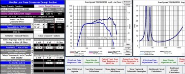
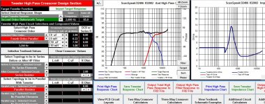
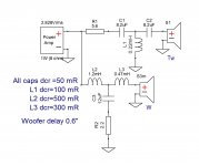
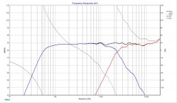
Woofer: circuit is a 2nd order Butterworth at 1500Hz w/ Zobel and 5-6dB of BSC. Tweeter: 4th order Butterworth at 3200Hz with L-Pad. PCD screen shots follow.
Note the rising response of the tweeter, not sure if this is worth trying to fix. Also the 1 kHz bump, is it something that needs a notch filter and worth the cost of parts to suppress? All input is welcome, thanks in advance.


Just looked up my profile and found I've been a member for 10 yrs, and have posted 3 times. Guess I'm the quit guy in the corner....
Moving on, as a learning exercise I put together a 7 liter, 2-way design, using the ScanSpeak 15W4524T02 and D2406-832002 Limited Edition drivers. My request is that more experienced members review and comment on the x-over and any improvements that can be made.
Woofer: circuit is a 2nd order Butterworth at 1500Hz w/ Zobel and 5-6dB of BSC. Tweeter: 4th order Butterworth at 3200Hz with L-Pad. PCD screen shots follow.
Note the rising response of the tweeter, not sure if this is worth trying to fix. Also the 1 kHz bump, is it something that needs a notch filter and worth the cost of parts to suppress? All input is welcome, thanks in advance.
If a speaker has a frequency response (FR) that is as flat as your upper graph, you're lucky. A 3 dB peak at 1kHZ is nothing compared to what most listening rooms will do to the sound by the time it reaches your ears. The rise at the high end just means grill cloth is OK. Too bad it rolls off below 50HZ, but it's probably still a very good sounding speaker. The only improvement I'd consider doing is adding a subwoofer and crossing it over at 90 - 100HZ . I love good low bass acoustically pretty flat down to 30HZ, but many are happy without it.
Yep, I'm obsessing over minutiae. To be honest the x-over went together so easily I began to wonder if something is missing.
Bass, the driver is a 6" mid-woofer so there is not a lot of opportunity their. Might look into a folded MLTL to see if that will extend the lower frequencies a bit...while keeping the same bezel dimensions.
Bass, the driver is a 6" mid-woofer so there is not a lot of opportunity their. Might look into a folded MLTL to see if that will extend the lower frequencies a bit...while keeping the same bezel dimensions.
"please attach zipped frd and zma files that you used and screenshot of the XO parts with values for X,Y and Z coordinates. Did you simulate baffle step response of the intended enclosure?"
Lojzek, Thanks for responding.
Requested files are attached. I haven't drawn the circuit since it's so simple, but the PCD screen shots for Woofer/Tweeter are included.
Baffle dimensions are 12-1/2"H x 7-3/4"W. Drivers location from the top; Tweeter 2-7/8" centered and Woofer, 8-1/8". Z dimension was not included in model.
Baffle Step and edge diffraction were modeled in Response Modeler with a 3/4" round-over.
Attachments
Looks pretty good to me! That peak in the woofer response is quite small and you may find it difficult to deal with it without causing a dip ") You could perhaps modify your zobel adding in an inductor as well and if carefully tuned you might get rid of it.
You could perhaps modify your zobel adding in an inductor as well and if carefully tuned you might get rid of it.
not having used Z offset you will probably find when it is taken into account the reverse null is no longer as good, and other variations.... without actual measurements on baffle though trying to determine the Z offset is a bit hit and miss, but a good estimate will be better than none at all.
Tony.
You could perhaps modify your zobel adding in an inductor as well and if carefully tuned you might get rid of it. not having used Z offset you will probably find when it is taken into account the reverse null is no longer as good, and other variations.... without actual measurements on baffle though trying to determine the Z offset is a bit hit and miss, but a good estimate will be better than none at all.
Tony.
Good call Tony.
Not sure how to determine the Z off-set. Any thoughts on how it might be approximated mechanically?
Once I have woofers in hand my intent is to build a test box and measure FR. Tweets are in hand. For now the goal is to sim a good starting point.
Thanks for your input.
Not sure how to determine the Z off-set. Any thoughts on how it might be approximated mechanically?
Once I have woofers in hand my intent is to build a test box and measure FR. Tweets are in hand. For now the goal is to sim a good starting point.
Thanks for your input.
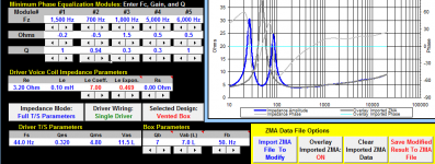
This is the difference between your simmed zma and the one I traced from woofer datasheet. You should make the inductive reactance part of the graph as close to the original as possible and then you will see that the filter you have now will change the FR. Try to make the XO circuit simpler. First start with a 2nd order woofer filter and 3rd order tweeter and if you can't achieve the results you like, increase the woofer to 3rd and tweeter to 4th. As Z offset, you can estimate it at about 15mm. If this won't work either, then introduce some LCR parallel filter before LP inductor.
Attachments
Thank you, Lojzek, for taking the time to look into this so carefully. My impedance file was obtained by tracing the mfg. spec with SPL Copy. Your graph is much more accurate. Do you mind describing your process or sharing the frd/zma files?
I intend to follow your design process to see if I can arrive at a simpler x-over. Will post again once I have something to share.
Thanks Again
I intend to follow your design process to see if I can arrive at a simpler x-over. Will post again once I have something to share.
Thanks Again
Try to compare these with your own.
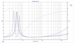
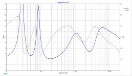
Lojzek, You've given me much to think about. Starting with a look at the woofer graphs, side by side, in XSim. Our impedance peaks are different, with mine higher. My graph has a narrower gap between peaks, though the lowest point is at the same frequency.
The noted difference lead me to look again at my original trace, taken from the spec sheet. My peak is an order of magnitude higher than spec. That's a problem. Interestingly, the simmed output does not have an order of magnitude issue. Still haven't resolved why the "simmed" file is not an order of magnitude high as well. This might just be sloppy work on my part.
Woofer x-over: Your ckt is more elegant and simpler, and with a higher order slope. What is the process for incorporating BSC into the a standard order configuration, as opposed to a separate ckt as I did? Otherwise, both outputs have a small rise at 1kHz and the similar overall shape. One last question, what do you mean by "woofer delay = 0.6 inches?" I would have expected any delay to be applied to the tweeter.
Thank you for taking the time to put this together. I feel as though I am gaining new insights already and haven't even delved into the tweeter section or W/T integration.
Hi Ed, since we are not designing any filters in the woofer tuning frequencies range, then it doesn't matter what these peaks look like. Our filter works in the kHz region and that's why the impedance curve in that should be realistic.
Beside SPL Copy, there is another particularly quick one that you will find at fprawn labs called FPGraphTracer. Demands the photos to be clear around curves so it locks precisely at once.
BSC is a procedure of creating the response curve that you make in the Baffle Diffraction Response Model module of RM, which you have already succesfully aplied when defining baffle measures and saving this response to the traced FR from manufacturer 2pi measurement.
I guess you wonder about using a separate LR filter additionaly to the LP filter. In general it doesn't matter how you manage to shape the curve of the frd file to create a final and normally looking low passed one, whether it's your way or anyone elses way, it depends what you want to achieve. Usually simple LP filters with larger values inductors are capable enough to make it work, but sometimes it has to be complicated and then your way will work better.
By 0.6" woofer delay, we mean to instruct the program to look at the woofer being 0.6" farther away from the tweeter, assuming our point of view (microphone position) is that tweeter and woofer are in front of us, on a flat baffle (not slanted). This is the standard convention when software adds additional phase delay (in degrees) to the woofer.
Yes, I see your point with respect to woofer impedance. Still my goal is to be as accurate in my work as possible.
FPGraph sounds like a program I want to check out. Seems SPLTrace has a hard time with Scanspeak graphs. Especially the older ones. For that matter any that do not have solid lines.
I like the simplicity of having the BSC incorporated into the LP, fewer components -> potentially lower cost. After ask the question I spent hours on the internet looking for the answer. Couldn't find anything that directly answered my question, though I came to the same conclusion as your explanation. Shape the response by adding inductance until a satisfactory result is achieved.
While contemplating the "0.6" question I realized that I was looking at this backward. I should have been looking at the woofer set-back on a vertical baffle. Instead my perspective was how much do I have to tilt the baffle back to align the tweeter.
My plan is to redo the FRD/ZMA files, and have new x-overs done next week. If you don't mind I'll shoot you the files so you can decide whether I gained the insight you shared. Regards, Ed
- Status
- This old topic is closed. If you want to reopen this topic, contact a moderator using the "Report Post" button.
- Home
- Loudspeakers
- Multi-Way
- Feedback Request: 2-way passive design