re "Oh come on you heartless peeps! I went through all that trouble of creating graphs and no one even cared."
Well I for one care, and most appreciate your efforts. Also thanks to everyone else who responded.
I found the graph which measures the response using REW most interesting. To me it shows that adding a 2.7 ohm resistor to a 4 ohm tweeter does nothing catastrophic but does alter the slope of the frequency response downward a bit.
"As you can see, at 10-20kHz this is about a 5 dB pad, but down at 1 kHz only a 3 dB pad, so the resistor introduces a new, 2 dB downwards slope relative to the original tweeter response"
What does surprise me though is that 2.7ohms reduces output by 5db. I would have expected a much lower 2 to 3 db.
eriksquires wrote"If you want to play with the original XSim files, you can find it via this link:
The LM-1 DIY Speaker is Available
Just delete the components you don't need.
Best,"
Well I'd love to but since it I'm using an active crossover the only thing in circuit with the tweeter amplifier is the speaker drive unit, for which I'm not sure if there's a spice model.
On the excellent Rod Elliot website "http://sound.whsites.net/index2.html" he mentions one way of simulating a loud speaker load is to place a 640uH inductor in series with a resistor" but that doesn't help my particular query.
Again thanks to all who responded: In the end I may just stay with the amp connected directly to the 4ohm tweeter because of the low power required for the tweeter. However the alternative of a resistor in series seems to be fine as well, apart from the slight downward frequency response.
Finally, if anyone can find a spice model of a real speaker unit, especially a tweeter, I'd be very interested to see it.
Well I'd love to but since it I'm using an active crossover the only thing in circuit with the tweeter amplifier is the speaker drive unit, for which I'm not sure if there's a spice model.
One doesn't know which that tweeter is and if you can provide that information then it might be easier to create a spice model for its impedance.
One doesn't know which that tweeter is and if you can provide that information then it might be easier to create a spice model for its impedance.
Its a Tymphany DX25SG05-04 1" Fabric Dome Tweeter 4 Ohm
see https://www.parts-express.com/tymphany-dx25sg05-04-1-fabric-dome-tweeter-4-ohm--279-171
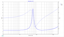
Yes, that's the smart empirical evidence. Clear as could be and the effect of tweeter inductance is small as should have been clear many posts earlier.Here is a typical tweeter, the XT25BG (as measured by yours truly), with and without a 2.7 Ohm Resistor. As you can see, at 10-20kHz this is about a 5 dB pad, but down at 1 kHz only a 3 dB pad, so the resistor introduces a new, 2 dB downwards slope relative to the original tweeter response:
It would also make sense to run REW on the amp output and see if anything like THD looks bad. (But if you want to worry, just listen to the horrible sounds that come from all tweeter in isolation.)
I'd say hardly worth fussing about. A bigger concern is protecting the tweeter from turn-on transients. With try-amping, wise to be using a mechanically robust tweeter. Of course, tri-amping is very smart configuration for a lot of important reasons.
I've spent many hours sorting out amp-happiness with electrostatic speakers as the load (which starts with a transformer and is very troublesome at both ends of the spectrum and a series resistor does horrible things to the FR). And the amp is called on to deliver high power into this terrible load. Here the demands on the amp, as others have said, it pretty light.
To make a long story shorter, best solution here is to add say just one or two Ohms to ensure the amp remains seeing a suitable load always. And, contrary to the widely held fantasies about power, I bet 4 watts resistor would last forever (just guessing here, but a finger on the resistor will tell you how it is surviving loud passages right away).
But here is a relevant question for this thread and I don't know the answer: how does damping factor affect (different kinds of) tweeters? Does DF matter for tweeters?
B.
Last edited:
DF affects speaker response in the way that its output impedance is equivalent to a resistor in series with speaker load. Solid state devices in general do not present a problem, tube amps might have more significant output impedance and we know that in that case, not to create too large frequency response variations thoughout the range, conjugate filters can be used to remedy that. Properly executed simulation can answer all the important questions, including DF "issue".
Beg to differ.Properly executed simulation can answer all the important questions, including DF "issue".
The question is whether making DF worse makes real-world tweeters behave any differently.* Where is the acoustic data?
We all know the theory. What are the facts?
B.
*nobody denies the theoretical relevance of DF to woofer behaviour although even with woofers, the audible differences may not be dramatic
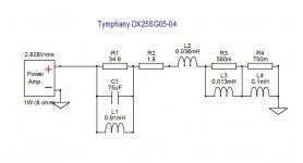
I'm just wondering, what is the origin of this schematic?
You're welcome. This exact impedance model is used in Visaton Boxsim.
@ Ben: Sorry, I don't have the means to conduct all the tests to provide you with factual data. Maybe someone else will give it a shot.
Last edited:
Couple of clarifications:
I use OmniMic and DATS, not REW.
Also, I misstated something. The electro-acoustical measurement for the XT25BG tweeter was done by me, but then imported into XSim for simulation.
So the trace with the 2.7 Ohm resistor was not measured but simulated. However, Xsim is never wrong.")
Best,
E
I use OmniMic and DATS, not REW.
Also, I misstated something. The electro-acoustical measurement for the XT25BG tweeter was done by me, but then imported into XSim for simulation.
So the trace with the 2.7 Ohm resistor was not measured but simulated. However, Xsim is never wrong.
Best,
E
Bento,
The wattage of a resistor is of course dependent on many things, including room size, overall speaker efficiency so I would not say 4 Watts was always the right value. With a tweeter in a multi-way what I do is use XSim, set the amp to 10-20% of maximum power, and then evaluate the heat dissipation of the resistors.
I do the opposite on the mid-woofer to evaluate power in coils and resistors as well.
If you are matching the impedance of the tweeter, that means the resistor will split the power. So if you are expecting 10 Watts through the tweeter, you'll need a 10 Watt resistor.
Best,
E
Last edited:
Always astonishes me to read posts by people with a good grasp of high school physics but more modest grasp of speaker reality.set the amp to 10-20% of maximum power,
Just estimating, but I'd say speakers use about 5% of the power folks at DIYaudio believe they do.
But even more important, the duty-cycle of music power is tiny esp if you are looking ar the time-constant life of a resistor temperature.
And all the more so on both points for tweeters.
In my earlier post, I was tempted to say 2 watts but thought that would seem extreme. What I did say was put your finger on the resistor and see if it is getting warm. You can sure pay for a whole lot of 4 watt resistors for the price of one 25 watt unit.
Reading this thread, you find a whole lot of missing information and a great amount of abstract speculation and sims replacing measurements. I'd stick a two-watt resistor in series (and test for heat) and the amp is happier (if not already perfectly happy) and the tweeter is fine too.
B.
Last edited:
I think we are in general agreement here, that in domestic circles the power dissipated in the typical dome tweeter or whatever is much less than 5 watts at the usual listening levels. So any series resistor used for level balancing or impedance matching need not be more than that of 5 watts. If one is fanatical about it, one could always mount the resistor on a heatsink of sorts but really that's hardly worth the effort.
When it comes to any change in frequency response one has to judge for themselves as to whether any such change is for the better or not. We don't listen to response curves but to music and that's why we tinker the way we do.
C.M
When it comes to any change in frequency response one has to judge for themselves as to whether any such change is for the better or not. We don't listen to response curves but to music and that's why we tinker the way we do.
C.M
bentoronto,
I truly regret trying to be helpful.
Lesson learned.
E
If always astonishes me how when one tries to be helpful readers construe a short, simple statement in the worst way and respond in the most offensive way possible. I regret that it did not occur to you that I was being short, instead of exhaustive in my explanations, while still trying to offer you a useful mechanism for estimating power usage, but expected you to use common sense.Always astonishes me to read posts by people with a good grasp of high school physics but more modest grasp of speaker reality.
I truly regret trying to be helpful.
Lesson learned.
E
Last edited:
Whatever your good intentions, you provided an analysis from "first principles" which was conceptually faulty and out of the ballpark by (1) having no relation to the realistic average power demands of a tweeter in a home environment and (2) not knowing or not mentioning the tiny duty-cycle of music and music peaks esp for tweeters (and the comparatively long heat time-constant of resistors).*I was being short, instead of exhaustive in my explanations, while still trying to offer you a useful mechanism for estimating power usage... I truly regret trying to be helpful.
Your recommendation was off base and misleading, perhaps inadvertently. But well intended, I am sure. It would have been better if you had responded in that light... instead of implicitly abusing me and yourself with a justification post and ending with a gratuitous sarcastic line.
B.
*yes, amps are on rare occasions called on to produce a big almost instantaneous peak for a tweeter (womens' chorus) so good to have the power there. But as far as heating a resistor, not much.
Last edited:
I'd stick a two-watt resistor in series (and test for heat)
Two-watt resistor is inadequate. For civilized use 5 W is enough, but I have seen countless burned 4 and 5 W resistors (and tweeters), usually after a party with some liquids involved.I think we are in general agreement here, that in domestic circles the power dissipated in the typical dome tweeter or whatever is much less than 5 watts at the usual listening levels. So any series resistor used for level balancing or impedance matching need not be more than that of 5 watts.
I've run a simulation of the circuit. I placed a 0.1 ohm resistor in series with the tweeter schematic which uses as an indicator of power, voltage and voltage phase changes in the circuit. Then I placed another resistor in series and stepped it from 0 to 6 ohms while at each step using a 2v ac source sweep from 1 hz to 30khz. I used the 0.1 ohm resistor to measure the results (voltage, power and voltage phase) of these iterations
If the circuit in the schematic accurately represents the tweeter then the simulation does show that adding a series resistor does change the power slope and power profile and voltage phase.
If the circuit in the schematic accurately represents the tweeter then the simulation does show that adding a series resistor does change the power slope and power profile and voltage phase.
Attachments
- Status
- This old topic is closed. If you want to reopen this topic, contact a moderator using the "Report Post" button.
- Home
- Loudspeakers
- Multi-Way
- adding resistor in series with tweeter in active sytem