The science is the height of the hollowed area is proportional to the diameter of the tweeter. Without a ring radiator the beam would only be as wide as the diameter will allow, it would beam 13,500hz, that's only if it's right in front of you, a 1" sweet spot. The ring radiator would effectively reduce the breakup at the top. Since I'm using it as a super tweeter, mono, and center of dash. I'm hoping I can reduce reflections from the side with treatment on the pillars, and the lens restricts longitudinal dispersion.
If I'm observing from the x plane looking at the zy plane, I want to narrow z(height) and maintain y(width). But if you squeeze z y responds like squishing a ball. So you must use treatment to correct. A parametric eq ain't gonna help just like ����
So basically I'm anticipating a bigass baffle is just going to be not helpful and impede my view
I hope my take on this is not skewed
Sent from my Pixel using Tapatalk
Yep, it basically takes the output of the diaphragm, concentrates it to a point, and reflects it 90 degrees.
Note that it only works over a very narrow bandwidth because the device is so small. (Same rules as any waveguide.) So with a 3" wide baffle, about the size of the one pictured in this thread, the beamwidth will be 180 degree from 4500Hz and up.
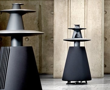
That's why the Beolab 5 looks the way it does. The tweeter at the top covers about 2-3 octaves, and the midrange below it covers another 2-3 octaves. It's a conventional three way loudspeaker with the drivers flipped 90 degrees. Note that the 'saucers' aren't just there for decoration; they're there to force the midrange and tweeter into radiating into half-space. (If they weren't there, the drivers would radiate in 360 degrees once the wavelengths exceed the diameter of the baffle behind the driver. IE, the tweeter would be radiating into 360 degree below 4500Hz if it wasn't for the 'platter' that's underneath it. The platter is there to reduce that angle to 180 degrees, which reduces 'floor bounce' and increases overall output.)
It's a waveguide, just a peculiar looking one.
You can also use the same technique for any angle you want; 90 degrees, 45 degrees, whatever. It doesn't have to be 180.
I've posted a bunch of threads on this, with measurements, if anyone's curious. Here's one:
A Nice Cheap Waveguide. - Car Audio | DiyMobileAudio.com | Car Stereo Forum
To me, the greatest thing about the lens is that the directivity collapses very gradually. IE, if I put a compression driver on a 90 degree waveguide that's 7" wide, the directivity is going to collapse from 90 degrees to 360 degrees very rapidly. IE, if the compression driver is playing 2000hz, the waveguide will constrain the directiviy of the wave becuase the waveguide is 7" wide, and so is 2000Hz. But at 1000Hz the wavefront is going to bend around the waveguide because it's too large for the waveguide to constrain it. With the SAW lens, when that happens, it's wrapping around an enclosure that's free of edges. You can see this in the measurements; there's a gradual change in directivity, instead of the abrupt change that you get with conventional waveguides.
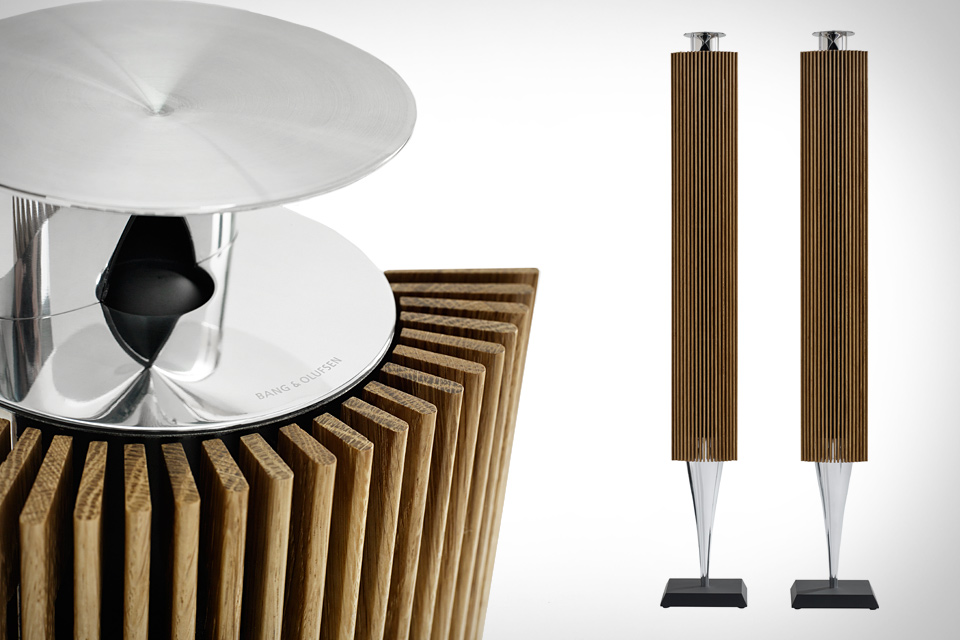
This use of diffraction-free enclosures is echoed across their entire line.
Last edited:
I did some more research to answer your question. The answer is conic sections, hyperbola. If a speaker sound emitted is a dipole and you imagine two cones and you cut perpendicular through the cones circle(s), acutely, you have a hyperbola. Depending on where you cut through will be the given dispersion angle.Hmm, looks like there is no real "hard" science behind this thing then (except for the concept of the lens)? That does not mean it is not an effective device tough")
In short as Bateman implied. It's the convergence of sound to one point and then the divergence exiting after the 90degree redirection. Pretty simple and elegant. I think you are over complicating the engineering of it. I didn't realise this topic dates back more than 2000 years


Sent from my Pixel using Tapatalk
To me these speakers are more or less a novelty kind of thing. I am not sure they offer any better quality sound vs. typical speakers. The reflected sound from the saucer will just smear the image, not to mention having to correct some of that in the xover. And the complicated xover probably not good for the sound.
A speaker radiating in all directions is not optimal for a vehicle application where it is subjected to many reflections. Control your high notes physically and control bass with eq.
If I were a gambling man I expect a stage to smear more without a lens, in a car that is. It's not utilized more because of licensing.
On top of that I'm only using one tweeter and out of the cross talk realm to begin with. I'll handle crosstalk on the midrange with the ambiophonic processing.
Sent from my Pixel using Tapatalk
One of the qualities of the xt25 thay most love is the top end bandwidth but many dislike because of the narrow directivity closer at the top. So essentially we are lensing it to focus on the part we do enjoy most. Either way out goals are mutual
Sent from my Pixel using Tapatalk
Sent from my Pixel using Tapatalk
I've been building these things for seven years now and I still can't make up my mind on them. I heard the B&O at CES 2016 and there are definitely audible HOMs. But the ones that I've built have worked well. The 'trick' is to use a 3/4" tweeter. Larger tweeters have a dip around 15khz due to the unequal pathlengths. (Larger diaphragm creates unequal pathlengths)
That makes sense, the 1" driver may have a higher concavity making the sides of the diaphragm a lot lower in relation to the very top partI've been building these things for seven years now and I still can't make up my mind on them. I heard the B&O at CES 2016 and there are definitely audible HOMs. But the ones that I've built have worked well. The 'trick' is to use a 3/4" tweeter. Larger tweeters have a dip around 15khz due to the unequal pathlengths. (Larger diaphragm creates unequal pathlengths)
Sent from my Pixel using Tapatalk
An externally hosted image should be here but it was not working when we last tested it.
So we have a Hyperbolic reflector paired with a parabolic path, and a ring radiator is like a doughnut surface vs an ellipsoidal. thats kinda cool its the exact opposite of an ellipse, mathematically that is differences between the two foci instead of the sum
Hi,
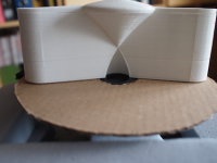
This is exactly what I did. Printed acoustic lens with DE7:
2017-07-08 Acoustic Lens DE7 image 1a.png
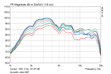
...and horizontal directivity 0-90°.
2017-07-08 Acoustic Lens DE7 55cm horizontal SPL Winkel 1.png
Note: The lens is just a first prototype, i.e. not necessarily ideal at this stage.
Gaga
what about a B&C DE5 ? (or DE 7)
This is exactly what I did.
Printed acoustic lens with DE7:2017-07-08 Acoustic Lens DE7 image 1a.png
...and horizontal directivity 0-90°.
2017-07-08 Acoustic Lens DE7 55cm horizontal SPL Winkel 1.png
Note: The lens is just a first prototype, i.e. not necessarily ideal at this stage.
Gaga
Attachments
Hi Patrick,
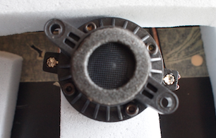
I did not use a gasket. There is a foam-ring terminating around the 'mouth' of the DE-7 (see image).
However, measurement was done with a very simple test-setup showing certainly some leaks between DE-7 and Lens... Thanks for pointing out!
I'll do a proper measurement and post here if of interest (may take a while though).
Gaga
Attachments

Yes please.Hi Patrick,
I did not use a gasket. There is a foam-ring terminating around the 'mouth' of the DE-7 (see image).
However, measurement was done with a very simple test-setup showing certainly some leaks between DE-7 and Lens... Thanks for pointing out!
I'll do a proper measurement and post here if of interest (may take a while though).
Gaga
I posted a "brain-dump" on how to build these things here:
http://www.diyaudio.com/forums/multi-way/163015-cloning-3200-speaker-400-a-10.html#post5126615
Did my best to sum up what HAS and HAS NOT worked in all of my obsessive reflector projects
http://www.diyaudio.com/forums/multi-way/163015-cloning-3200-speaker-400-a-10.html#post5126615
Did my best to sum up what HAS and HAS NOT worked in all of my obsessive reflector projects
- Status
- This old topic is closed. If you want to reopen this topic, contact a moderator using the "Report Post" button.
- Home
- Loudspeakers
- Multi-Way
- 3d Printed acoustic lens, XT25, Thingiverse