...If I move the holes towards the mouth of the horn, wouldn't similar dips lower in frequency appear?
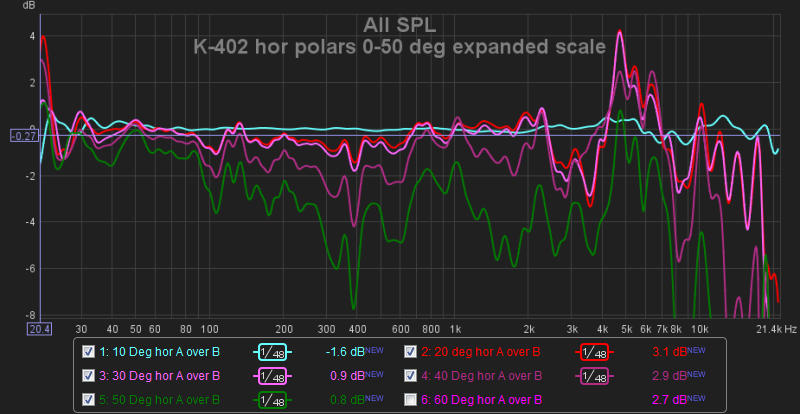
Yes, but if you move the ports out to a point corresponding to ~1 kHz, then you have the option of using two sets of drivers in the crossover region to compensate for the local loss of SPL on-axis. The normalized off-axis SPL losses (normalized to 0 degree FR) are fairly mild in the cases that I've seen--just below 400 Hz in this case, and the smoothing here--1/48th octave--which is too rough. The design horn coverage half angle is 45 degrees in this case:
The same normalized data but smoothed with psychoacoustic smoothing, more indicative of human hearing perception:
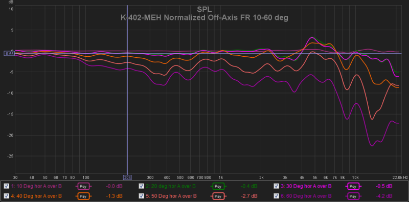
The compression driver used here is a P.Audio BM-D750 series I, and the two woofers used are Crites CW1526C cast frame 15".
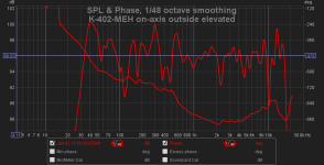
The zero degree on-axis frequency response and phase after EQ (note the vertical axes resolution in each of these plots):
Attachments
Last edited:
Hi Cask
Its interesting that you have those DIPs at 400 Hz, where I believe you cross over and attribute them to the woofer tap holes. I've don't see anything like that in my Synergy which uses 3/8" wide slots about 1" long with XO at 1050 Hz. Perhaps that size and aspect ratio allows them to effectively hide in the corners without disrupting the pattern.
I do have to admit that I've got limited polars for my horn - I just take them across angle corresponding to my listening couch. Its a corner horn and I've never taken it outside and regret that. I have a couple of excuses - one that I couldn't take the corner outside with it and two that I was rehabbing from open heart surgery while developing it. In room, I have a ceiling reflection that messes up measurements at the LP but those taken at 1m or gating out the ceiling reflection don't show dips at XO similar to yours. Being able to move the large woofer holes further from the horn throat is one of the benefits of doing a 3 way synergy that is manifested by this. Nevertheless, I'm strongly tempted to try one in your style for my next effort.
What are reasonable goals for the constancy of directivity of a wooden conical horn? I was happy to get within +/- 2db over the limited range of angles corresponding to my listening positions on the couch after eqing flat at the middle of it.
Hi Cask
Its interesting that you have those DIPs at 400 Hz, where I believe you cross over and attribute them to the woofer tap holes. I've don't see anything like that in my Synergy which uses 3/8" wide slots about 1" long with XO at 1050 Hz. Perhaps that size and aspect ratio allows them to effectively hide in the corners without disrupting the pattern.
Those are normalized off-axis SPLs based on the on-axis SPL, so unless you were doing outside/elevated off-axis measurements, you might not have not noticed the polar off-axis notch effect. I find that I cannot detect the extremely small off-axis polar disruption shown above by ear, and having single-point source and directivity to below 100 Hz results in an MEH whose listenability and in-room performance that is difficult to characterize in words. "Really good" would be a conservative choice of words.
What are reasonable goals for the constancy of directivity of a wooden conical horn?
If you base the geometry of your straight-sided horn on some profile that uses the same expansion principles as the K-402 then I'd say that the off-axis polars can be quite uniform, as shown above. The non-flat performance that you see at higher frequencies are governed mostly by the compression driver's phase plug and exit throat geometries. Change the compression driver and those anomalies will change.
The smooth tractrix mouth roll-out without sharp chine edges on the horn surface is important near the lower end of the passband to avoid impedance bounces and polar disruptions. It's difficult to use wood products to do that smooth roll out and end up with a horn wall that's stiff enough. I do recommend tractrix or spherical wave (Klangfilm) mouth expansions.
The horn doesn't have to be a "conical" x^2 area expansion rate. In fact, the horn I'm using doesn't have a conical expansion, but about 2/3'rds of the horn uses straight sides (which aren't "conical").
I was happy to get within +/- 2db over the limited range of angles corresponding to my listening positions on the couch after eqing flat at the middle of it.
As far as off-axis polar stability, I find that the ability to get within the limits shown above introduces another level of performance that I find the ears delight in hearing in-room. Perhaps I'll have a DIY horn that I can share in the near future for others to hear. It's a big horn--about 35 lbs worth once all the stiffening and beefing up of the base horn is done.
The horn profile shown above was designed specifically for the problem of equal frequency response coverage for cinema use. It represents a qualitative difference in off-axis coverage performance that I've not experienced in other horns that I've examined or tested.
Chris
Could you briefly describe the relationship or solver used
Hornresp models the complete electro-mechano-acoustical lumped-element equivalent circuit of the multiple entry horn loudspeaker, solving for acoustical impedances, volume velocities and sound pressures through the system. Needless to say, it is not a trivial task - there are no simple relationships or solvers that can be used.
(The acoustic interactions in multiple entry and tapped horn speakers are particularly complex. The only way to come up with reasonable predictions is to analyse the complete equivalent circuit).
So you verified your "complete lumped multiple entry model" using what kind of informal input parameter parametrics, and comparisons to actual measurements...if you can recall?(The acoustic interactions in multiple entry and tapped horn speakers are particularly complex. The only way to come up with reasonable predictions is to analyse the complete equivalent circuit).
Chris
So you verified your "complete lumped multiple entry model" using what kind of informal input parameter parametrics, and comparisons to actual measurements
I haven't done any predicted versus measured comparisons myself, but perhaps someone who has built a multiple entry system using Hornresp to assist with the design process, might care to comment on the accuracy of the predictions - bearing in mind that Hornresp calculates power response, not pressure response.
Hey guys!
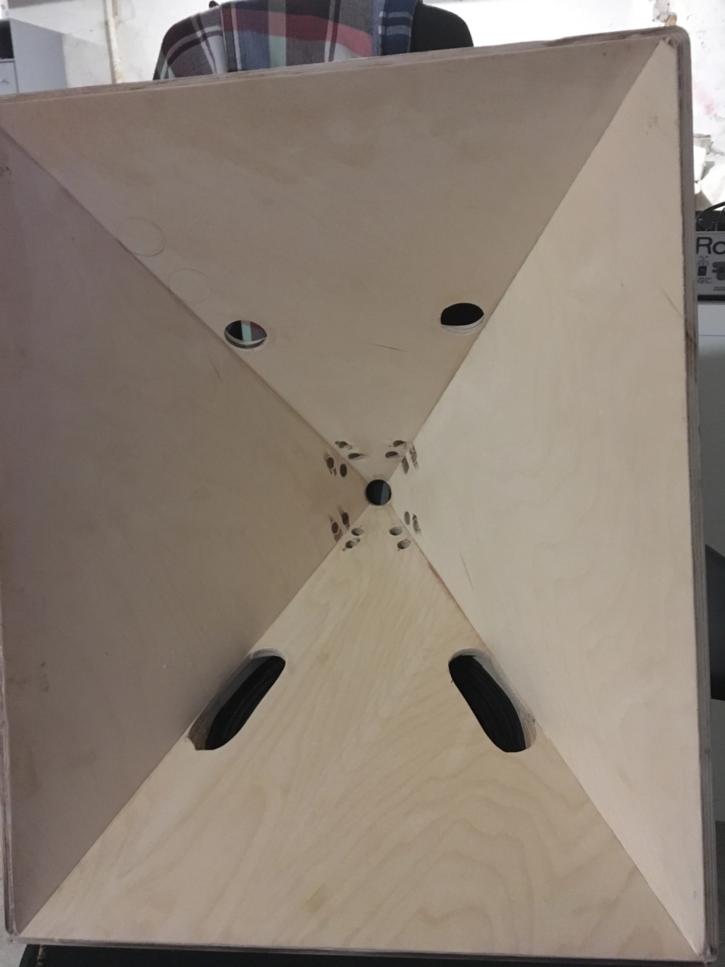
I've played around with the holes on my prototype horn.
This is what I got as a result after drilling a set of holes 2cm down along the horn walls.
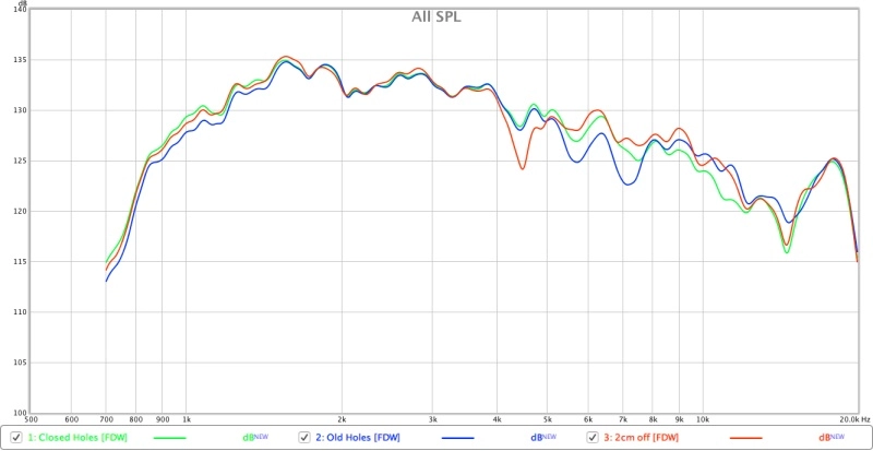
It moved the dip from round 7k to 4.5k
I also noticed the following:
On the prototype - the mid taps lay half a centimeter away from the edge
On the "finished" the taps lay so that they "touch" the edge.
On the prototype there is an approx 5db dip
On the "finished" the dip is 10db.
I based my decision to drill just by the edge because I found some comments stating that it is better in terms of off axis freq response.
What are your experiences?
I've played around with the holes on my prototype horn.
This is what I got as a result after drilling a set of holes 2cm down along the horn walls.
It moved the dip from round 7k to 4.5k
I also noticed the following:
On the prototype - the mid taps lay half a centimeter away from the edge
On the "finished" the taps lay so that they "touch" the edge.
On the prototype there is an approx 5db dip
On the "finished" the dip is 10db.
I based my decision to drill just by the edge because I found some comments stating that it is better in terms of off axis freq response.
What are your experiences?
Frequency dependent windowing doesn't always help when trying to analyse dips, sometimes the overall area can seem depressed when it is actually a bunch of very sharp dips. Looking at 1/48 or 1/12 smoothing might show the problem better.
I have a couple of thoughts (not based on my own experience). Bill built two versions of his cosine horn and when he put the holes across the corners the result was not as good as when there was a bit of a gap, I'm sure Bill can tell you more about it himself.
Another thing you could try is a layout more like the Cosine for the mids, have two on the top and two on the bottom rather than one on each side.
Use one hole per driver instead of two, or you could just use one on top and one on the bottom as a test with two holes each. Fill in the side holes and try and make the mid ports be as equal in distance side to side as top to bottom without going too far from the corners.
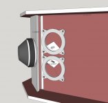
When I see your picture of the two holes almost joining in the corners it doesn't look great from a diffraction point of view.
In the image the ports look quite deep, as nc535 has said before if you frustrumize the back of the port you can reduce the depth of the port and get away with a smaller diameter port. Not sure if you have already tried those things but could be worth thinking about if you haven't.
I have a couple of thoughts (not based on my own experience). Bill built two versions of his cosine horn and when he put the holes across the corners the result was not as good as when there was a bit of a gap, I'm sure Bill can tell you more about it himself.
Another thing you could try is a layout more like the Cosine for the mids, have two on the top and two on the bottom rather than one on each side.
Use one hole per driver instead of two, or you could just use one on top and one on the bottom as a test with two holes each. Fill in the side holes and try and make the mid ports be as equal in distance side to side as top to bottom without going too far from the corners.
When I see your picture of the two holes almost joining in the corners it doesn't look great from a diffraction point of view.
In the image the ports look quite deep, as nc535 has said before if you frustrumize the back of the port you can reduce the depth of the port and get away with a smaller diameter port. Not sure if you have already tried those things but could be worth thinking about if you haven't.
I think having the midrange holes in the corners is better, all things being equal. Problem is, all things aren't equal usually. It's a lot more important to keep all the midrange ports within 1/4 wavelength a their upper crossover frequency, otherwise weird responses can happen, particularly off-axis. That includes the midrange ports that are furthest from each other (the ones diagonally opposite across the tweeter throat). I really like the acoustic filtering obtainable using small midrange drivers between tweeter and woofer, but the midranges can be kind of easy to mess up if you are crossing them high, positioning them in the horn can be tricky. One other thing, I think you'll find that you don't need as many midranges as Danley uses, he's doing pro high SPL stuff. In your living room, on a horn, one or two midranges will be plenty. The tweeter will probably run out of gas first.
Hmm,
a lot of food for thought and experiment")
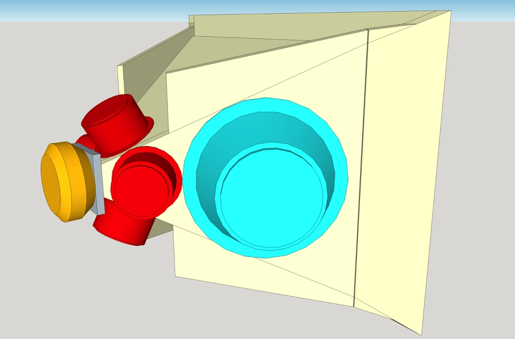
I played with enlarging the ports for the woofer.
In a few steps, I extended them until the area of the ports was as big as the area of the SH50 that mr.Bateman supplied earlier.
In the picture, the port is 10cm long and 3.2cm wide.
I also put a plywood ring to add some space between the woofer and the horn, which didn't really matter since the woofer wasn't touching (but I just wanted to make sure..)
The next thing I did was to fustrumize the back side of the port pointing the center.
I figured that even the port being 3.2 cm wide, the distance from the membrane to the wood was way less, so it made a lot of sense to take a bit of that out.
In conclusion, I think it was the space between the cone and the corner of the port entrance that was the problem. The air was squeezing through a tight slit. And it was very pronounced in kicks, as the membrane goes even closer to the horn, so the most air had to go out when the gap was the narrowest.
Thanks a lot for all the input!
I'll do some experiments with the mid taps tomorrow!
You guys are amazing!
a lot of food for thought and experiment
I played with enlarging the ports for the woofer.
In a few steps, I extended them until the area of the ports was as big as the area of the SH50 that mr.Bateman supplied earlier.
In the picture, the port is 10cm long and 3.2cm wide.
I also put a plywood ring to add some space between the woofer and the horn, which didn't really matter since the woofer wasn't touching (but I just wanted to make sure..)
The next thing I did was to fustrumize the back side of the port pointing the center.
I figured that even the port being 3.2 cm wide, the distance from the membrane to the wood was way less, so it made a lot of sense to take a bit of that out.
In conclusion, I think it was the space between the cone and the corner of the port entrance that was the problem. The air was squeezing through a tight slit. And it was very pronounced in kicks, as the membrane goes even closer to the horn, so the most air had to go out when the gap was the narrowest.
Thanks a lot for all the input!
I'll do some experiments with the mid taps tomorrow!
You guys are amazing!
If I can be so bold, I don't find what I infer as your logic to be compelling. I suspect that if you hadn't made the woofer holes too small to begin with or if you had been placing 12" woofers instead of 10" woofers over those very same holes, you never would have come to your second conclusion.
I think that perhaps the bulk of your holes were under the suspension/surround instead of under the cone and that is why a restriction was created as the cone reached its highest outward excursion. I agree that is a condition to be avoided but I don't think it says as much about the aspect ratio of the port holes as about where the hole should be relative to the boundary between the cone and surround.
Frustrumization and the woofer spacers as well as enlargement either by elongation or higher diameter all contribute to relieving that restriction. I think that can be done even with elongated rather than round holes and the elongated holes can be better for the polars - but that is really hard to say definitively without a large amount of FEM or BEM simulation or drilling and filling of a prototype.
Fortunately, you don't need to find the best hole size and shape, just one that works well enough for your intended purposes.
Conclusion #2 goes to the trash
I'm using a pair of 10" drivers and my priority was cramming the taps as close to the throat as possible in order to be able to cross at the frequencies of desire following the 1/4 wavelength rule.
As for the port sizes, I used what worked best in hornresp... also minding the 1:10 compression ratio?
(1" tap for 10" speaker)
So for the 10" woofers, the taps are:
16.5 cm from the throat + 5.5 cm CD internal path = 22cm (1/4 WL of 400Hz)
The distance between the furtherest taps is 32.1cm
The area of the intersection of the horn where the ports start is 501 cm2
For the 4" mids, the taps are:
3cm from the throat + 5.5 cm CD int. path = 8.5cm (1/4 WL of 1000Hz)
The distance between the furtherest taps is 8.2cm
The area is 33,1 cm2
(note that the plate that the CD is mounted on is 0.4cm thick and I didn't include it in this calculation)
..so in order to get the taps right, it was necessary to put the taps over the suspension
I hope that fustrumizing inner side of the (now elongated) woofer taps would help
Thanks again for the help!
I'll post a plot of the THD of the woofers when I get the boxes closed.
(It's quite of a pain making the boxes the same having that I "completed" one first...)
Last edited:
Did you measure the distanced from the beginning of the port or from the center of the port?
Hmm,
a lot of food for thought and experiment
I played with enlarging the ports for the woofer.
In a few steps, I extended them until the area of the ports was as big as the area of the SH50 that mr.Bateman supplied earlier.
In the picture, the port is 10cm long and 3.2cm wide.
I also put a plywood ring to add some space between the woofer and the horn, which didn't really matter since the woofer wasn't touching (but I just wanted to make sure..)
The next thing I did was to fustrumize the back side of the port pointing the center.
I figured that even the port being 3.2 cm wide, the distance from the membrane to the wood was way less, so it made a lot of sense to take a bit of that out.
In conclusion, I think it was the space between the cone and the corner of the port entrance that was the problem. The air was squeezing through a tight slit. And it was very pronounced in kicks, as the membrane goes even closer to the horn, so the most air had to go out when the gap was the narrowest.
Thanks a lot for all the input!
I'll do some experiments with the mid taps tomorrow!
You guys are amazing!
..so in order to get the taps right, it was necessary to put the taps over the suspension
What you need to do is use the "wings" like Bill did to give extra area to bolt the woofers down to, you can then centre the woofers over the ports better. You can still add them on it is just more work than planning to do it that way from the start
You might have avoided doing that due to putting the midranges on the sides. If you add the wings you can mount the midranges in the same way to top and bottom and get them better centred over the ports too.
It depends on the size of your horn and the angle, if you can fit two 10"'s on one side.
On a 90x60 there is more room, if yours is 60x60 it might be more of a squeeze.
This image of Bill Cosine shows what I mean. The drivers he used are smaller but the principal is the same if you can fit them in.

It requires a bit of planning and CAD is useful for working out if the woofer will fit where you want it without the ports being too close to the edge of the driver.
If you lost the midrange from the side you could pull the woofer back further towards the throat and have the driver centred over the ports better. Probably too late now you have cut them bigger as it would be pretty hard to fill
That being said Art Welters SynTrip has the 10" drivers pretty close to the edge and I have seen a few Danley pictures where the woofers don't seem to have much room either.
On a 90x60 there is more room, if yours is 60x60 it might be more of a squeeze.
This image of Bill Cosine shows what I mean. The drivers he used are smaller but the principal is the same if you can fit them in.
It requires a bit of planning and CAD is useful for working out if the woofer will fit where you want it without the ports being too close to the edge of the driver.
If you lost the midrange from the side you could pull the woofer back further towards the throat and have the driver centred over the ports better. Probably too late now you have cut them bigger as it would be pretty hard to fill
That being said Art Welters SynTrip has the 10" drivers pretty close to the edge and I have seen a few Danley pictures where the woofers don't seem to have much room either.
Attachments
here is a pic of my horn with 2 mids per side exported from Sketchup to give you a better idea of what we are talking about and how it can work out. This is just to clarify; I'm not suggesting you need to redo things this way. I think you are on the track to making yours work.
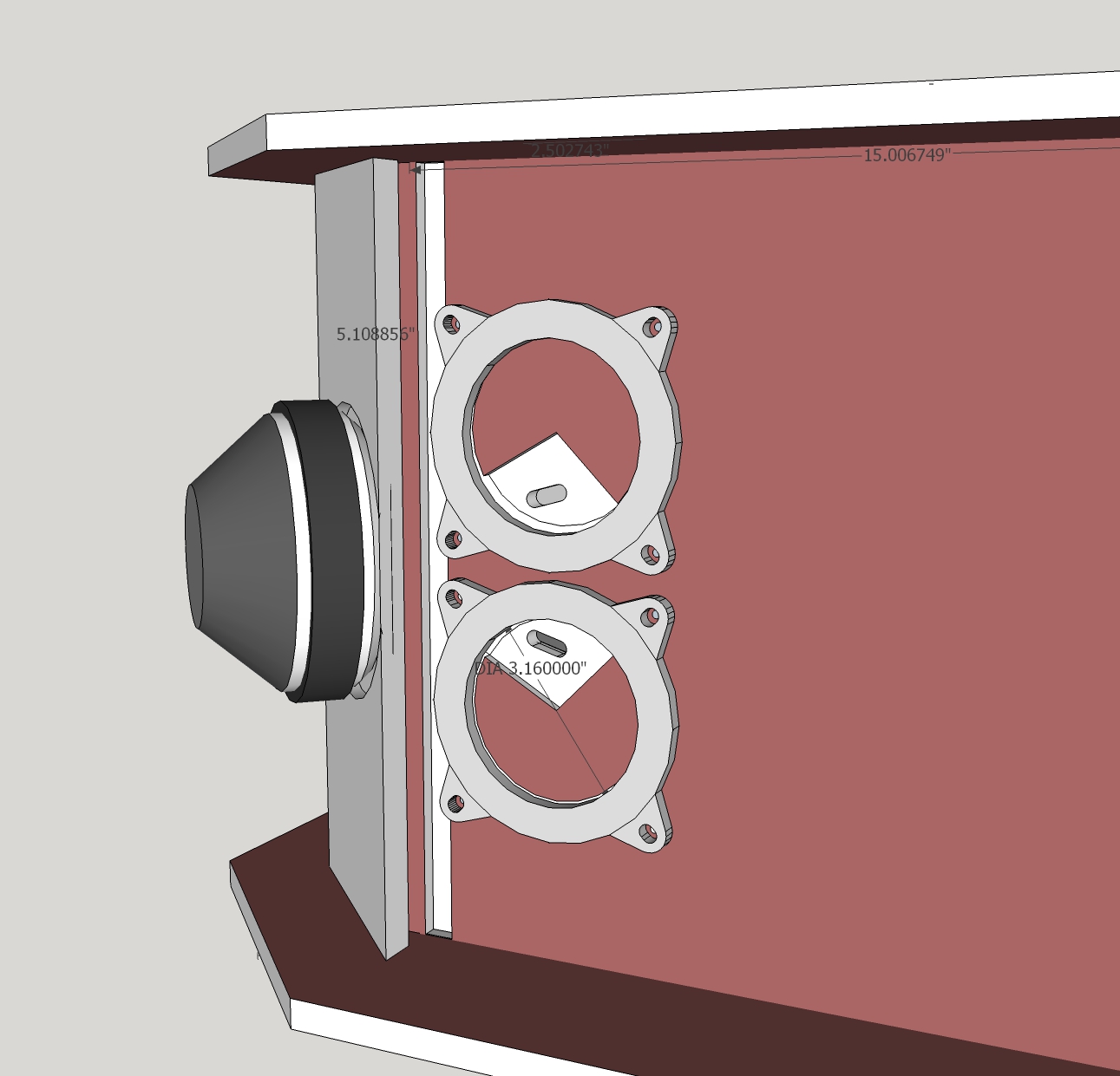
I'm showing just the footprint of the mids, which extends to almost the inside edge of the surround. I actually had to chamfer the inside of the trench I routed for the surround to prevent it from being hit by the cone. I also cleared out the horn wall around the hole down to just 6 mm thickness and then as a final tune chamferred the edges of the slots and then mudded in the thinned area in a tapered fashion to displace air. You can see the ports, which are tight into the corners of the horn, are quite small but my THD plots are exemplary.
Woofer holes? I put the 15" woofer in a separate box - a bass bin supporting the horn bringing the CD tweeter up to ear height.
Attachments
I wish I was as good in planning nc535.
There are many things about working with wood and layout that I didn't know when I started... it's been a pretty steap learning curve
It is also the first loudspeaker I've ever built...
And the first dropsaw I ever operated
I've had at my disposal a dropsaw, a drilling machine, a file and some sand paper
- Home
- Loudspeakers
- Multi-Way
- Unity / Synergy Horn Build