So I think the reason of using high quality cap and resistor is the parasitic inductance are kept to minimum. But in a notch filter where you already have an inductance in series, then does it matter? Therefore electrolytic caps shouldn't matter right since you already have the inductance in series. As far as Q, with the resistor in series, your Q probably is determined by the resistor not by the parasitic losses of the cap.
Anyway, that is my reason.
Anyway, that is my reason.
So I think the reason of using high quality cap and resistor is the parasitic inductance
are kept to minimum.
Stability of the parts' values, and hence the notch frequency, is very important in a notch filter.
Electrolytics don't work very well in this respect.
Stability is a valid concern but within a few percent shouldn't make much difference in freq. response, unless you refer to stability vs. voltage and freq?
ESR is somewhat negated since you already have the series resistor, unless there is a secondary affect in which case could you explain?
ESR is somewhat negated since you already have the series resistor, unless there is a secondary affect in which case could you explain?
Last edited:

Parasitic inductance is hardly relevant to capacitors or resistors which have very little of either. 
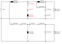
Let's look at a typical LCR notch circuit, designed to take out the typical 6kHz cone resonance of a 6" driver. Below. Based on this clever idea: mh-audio.nl - Home
Typically a 6" driver is driven by 20V peak to peak when loud. Unless I am losing my mind, that LCR notch has a "Q" around 4, simply because of the 2.2R resistor employed. This means that every reactive component sees about 80V. A 50V non-polar electrolytic is seeing about 80V.
I wouldn't ask that of an electrolytic. Makes much more sense to use a 250V MKP type. Aside from which, a NP electrolytic is quite unstable on capacitance with time. They wander as they age and dry out. Which affects a fairly precise tuning.
I don't suppose the 7.5R plus 18uF impedance correction is very critical. A NP makes sense there with a smallish ESR around 0.5R..
I'd also use aircoils in an LCR. Why? With a high "Q" currents are exaggerated and non-linear effects (and noise) increase. It is simplicity itself to include resistance of a coil in the overall LCR circuit. The resistor just gets smaller.
I like the idea of using aircoils in bafflestep compensation too, but it's not a cure-all since speakers are one big ferrite too. In other words, it helps, but not perfect.
Attachments
- Status
- This old topic is closed. If you want to reopen this topic, contact a moderator using the "Report Post" button.