Hello all,
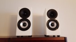
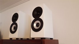
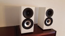
Here is an illustrated guide to make a pair (or many) of my Dayton Mini Monitor speakers. They are small low-budget speakers which fit very well to small rooms as for example TV speakers. I have made 5 pairs of these speakers for customers and as presents, and they have been very well received. To me, they provide the best bang for buck I have so far seen on my DIY speaker building career of 10 years. As of today, you can get all the electronics used for these speakers under 100€ per pair. With cabinets and Breeze Audio TPA3116 Bluetooth amplifier from eBay the cost is still under 200€. Tremendous value for DIY. The pictures are as attachments at the bottom of the post. Feel free to ask any questions you might have.
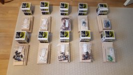
To start with, these are the parts for a pair of the speakers:
Electronics:
Dayton DA115-8 Woofer, 2 pcs
Dayton ND25FW-4 Tweeter, 2 pcs
0,65mH 0,71mm^2 air core coil, 2 pcs
0,33mH 0,71mm^2 air core coil, 2 pcs
4,7uF polyester capacitor, 2pcs
0,22uF polyester capacitor, 2 pcs (this goes parallel to the 0,65mH coil on woofer crossover)
15 uF electrolytic capacitor, 2 pcs
8,2 Ohm 10W resistor, 2 pcs
2,2 Ohm 10W resistor, 2 pcs
2,7 Ohm 10W resistor, 2 pcs
0,82 Ohm 10W resitor, 2 pcs
Other parts:
Boards from 15mm BB plywood (or equivalent material with similar thickness)
270x155mm, 4 pcs (sides)
270x130mm, 2 pcs (front baffle)
240x100mm, 2 pcs (back baffle)
155x100mm, 4 pcs (top and bottom)
32mm internal diameter 200mm long piece of plastic pipe for BR tube, 2 pcs
8mm recycled felt for damping
Speaker cable for internal wiring (I used 1,5mm^2 cable as I had that already)
Connectors (terminal cup or screws, I used a cup since I got it cheaper), 2pcs
Rubber feet 10mm high or speaker spikes around 10mm high, 8 pcs
Bunch of screws
Phase I is to assemble the cabinets. Wood glue is sufficient for a cabinet of this size unless you plan on beating it with a sledgehammer. The easy way is to glue the back, top and bottom to one of the side boards, then gluing the other side board onto it. The front baffle needs some routing and drilling, so it's better done first before gluing.
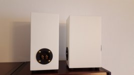
Phase II Time to bring out your router and drill. The centers of the driver cutouts are 65mm from sides and top for tweeter, and 65mm from sides and 170mm from top for woofer. To be more exact, you need to route a 104mm diameter 3mm deep seating groove for the tweeter flange along with a 70mm diameter hole in the center of it. The woofer needs a 93mm diameter hole with a chamfer on the back side of the baffle board. I used a 10mm wide 45 degree router bit for the chamfer. As you have the power tools out anyway now, you might as well drill the reflex tube hole (mine was 36mm due to 2mm wall thickness of the tube) and the hole for the terminal cup if you use one for the speakers. The center for the reflex tube on the bottom of the enclosure is 65mm from sides and the back baffle. The center for the terminal cup is free to choose, but I recommend 65mm from sides and 65mm from bottom of the cabinet on the back baffle.
Phase III The insides of the enclosure should be lined with the 8mm felt excluding the front baffle and the bottom which will have the crossover and reflex tube glued to it. Regular wood glue works fine when gluing the felt. When you glue the reflex tube, use a very strong adhesive for a secure bond. I used a high strength construction epoxy as the glue for it. Glue the felt first, then the reflex tube. You'll have an easier time this way. Last, glue the front baffle to the rest of the enclosure.
Phase IV Finish the enclosure. I used a 10mm deep curving router bit to create a flange to the outgoing part of the reflex tube, and if you have a router I highly recommend you do it as well do minimize the port noises. Note that this shortens the actual functioning length of the reflex tube to 190mm. If you plan on not routing the rounding for the tube, use a shorter tube. As the reflex tube opens under the enclosure, you need to lift it off the surface it's going to sit on. The rubber feet are optimal for this as they also isolate the travel of vibrations between the speaker and the surface they're sitting on. I sanded the edges slightly to create small diameter rounding, I'm not a fan of sharp 90 degree angles.
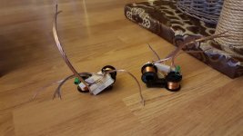
Phase V Solder the crossover along with the wires for input and output. The 0,22uF capacitor that's in the part list but not on the picture goes parallel to the 0,65mH coil on the woofer. Simply across the wires on the coil. The greyed out resistors are resistances of the coils, don't mind them. The selection of crossover components is free, as long as the values are correct. I recommend a reasonable quality capacitor for the tweeter as it's going to be directly on the signal way. An electrolytic capacitor is sufficient for the woofer zobel circuit (the cap and resistor combo) as it's not on the signal way. Main thing to remember is to never align the coils on the same direction. Easy way to solve this is simply to space the coils a bit apart and rotate the other one 90 degrees to its side.
Phase VI Attach the crossover, drivers, terminal cups and rubber feet. Main thing to remember here is the reverse polarity on the tweeter. Tweeter already has a gasket on the frame, so no need for it. I didn't use any gasket for the woofer either, and air leak test proved it's still airtight. I used hotmelt glue for attaching the crossover to the bottom of the enclosure and the side of the reflex tube.
Phase VII Grab your favourite beverage, sit in a nice chair, and put on some music. It's time to enjoy the fruits of your labour for a while...
Here is an illustrated guide to make a pair (or many) of my Dayton Mini Monitor speakers. They are small low-budget speakers which fit very well to small rooms as for example TV speakers. I have made 5 pairs of these speakers for customers and as presents, and they have been very well received. To me, they provide the best bang for buck I have so far seen on my DIY speaker building career of 10 years. As of today, you can get all the electronics used for these speakers under 100€ per pair. With cabinets and Breeze Audio TPA3116 Bluetooth amplifier from eBay the cost is still under 200€. Tremendous value for DIY. The pictures are as attachments at the bottom of the post. Feel free to ask any questions you might have.
To start with, these are the parts for a pair of the speakers:
Electronics:
Dayton DA115-8 Woofer, 2 pcs
Dayton ND25FW-4 Tweeter, 2 pcs
0,65mH 0,71mm^2 air core coil, 2 pcs
0,33mH 0,71mm^2 air core coil, 2 pcs
4,7uF polyester capacitor, 2pcs
0,22uF polyester capacitor, 2 pcs (this goes parallel to the 0,65mH coil on woofer crossover)
15 uF electrolytic capacitor, 2 pcs
8,2 Ohm 10W resistor, 2 pcs
2,2 Ohm 10W resistor, 2 pcs
2,7 Ohm 10W resistor, 2 pcs
0,82 Ohm 10W resitor, 2 pcs
Other parts:
Boards from 15mm BB plywood (or equivalent material with similar thickness)
270x155mm, 4 pcs (sides)
270x130mm, 2 pcs (front baffle)
240x100mm, 2 pcs (back baffle)
155x100mm, 4 pcs (top and bottom)
32mm internal diameter 200mm long piece of plastic pipe for BR tube, 2 pcs
8mm recycled felt for damping
Speaker cable for internal wiring (I used 1,5mm^2 cable as I had that already)
Connectors (terminal cup or screws, I used a cup since I got it cheaper), 2pcs
Rubber feet 10mm high or speaker spikes around 10mm high, 8 pcs
Bunch of screws
Phase I is to assemble the cabinets. Wood glue is sufficient for a cabinet of this size unless you plan on beating it with a sledgehammer. The easy way is to glue the back, top and bottom to one of the side boards, then gluing the other side board onto it. The front baffle needs some routing and drilling, so it's better done first before gluing.
Phase II Time to bring out your router and drill. The centers of the driver cutouts are 65mm from sides and top for tweeter, and 65mm from sides and 170mm from top for woofer. To be more exact, you need to route a 104mm diameter 3mm deep seating groove for the tweeter flange along with a 70mm diameter hole in the center of it. The woofer needs a 93mm diameter hole with a chamfer on the back side of the baffle board. I used a 10mm wide 45 degree router bit for the chamfer. As you have the power tools out anyway now, you might as well drill the reflex tube hole (mine was 36mm due to 2mm wall thickness of the tube) and the hole for the terminal cup if you use one for the speakers. The center for the reflex tube on the bottom of the enclosure is 65mm from sides and the back baffle. The center for the terminal cup is free to choose, but I recommend 65mm from sides and 65mm from bottom of the cabinet on the back baffle.
Phase III The insides of the enclosure should be lined with the 8mm felt excluding the front baffle and the bottom which will have the crossover and reflex tube glued to it. Regular wood glue works fine when gluing the felt. When you glue the reflex tube, use a very strong adhesive for a secure bond. I used a high strength construction epoxy as the glue for it. Glue the felt first, then the reflex tube. You'll have an easier time this way. Last, glue the front baffle to the rest of the enclosure.
Phase IV Finish the enclosure. I used a 10mm deep curving router bit to create a flange to the outgoing part of the reflex tube, and if you have a router I highly recommend you do it as well do minimize the port noises. Note that this shortens the actual functioning length of the reflex tube to 190mm. If you plan on not routing the rounding for the tube, use a shorter tube. As the reflex tube opens under the enclosure, you need to lift it off the surface it's going to sit on. The rubber feet are optimal for this as they also isolate the travel of vibrations between the speaker and the surface they're sitting on. I sanded the edges slightly to create small diameter rounding, I'm not a fan of sharp 90 degree angles.
Phase V Solder the crossover along with the wires for input and output. The 0,22uF capacitor that's in the part list but not on the picture goes parallel to the 0,65mH coil on the woofer. Simply across the wires on the coil. The greyed out resistors are resistances of the coils, don't mind them. The selection of crossover components is free, as long as the values are correct. I recommend a reasonable quality capacitor for the tweeter as it's going to be directly on the signal way. An electrolytic capacitor is sufficient for the woofer zobel circuit (the cap and resistor combo) as it's not on the signal way. Main thing to remember is to never align the coils on the same direction. Easy way to solve this is simply to space the coils a bit apart and rotate the other one 90 degrees to its side.
Phase VI Attach the crossover, drivers, terminal cups and rubber feet. Main thing to remember here is the reverse polarity on the tweeter. Tweeter already has a gasket on the frame, so no need for it. I didn't use any gasket for the woofer either, and air leak test proved it's still airtight. I used hotmelt glue for attaching the crossover to the bottom of the enclosure and the side of the reflex tube.
Phase VII Grab your favourite beverage, sit in a nice chair, and put on some music. It's time to enjoy the fruits of your labour for a while...
Attachments
Last edited:
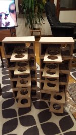
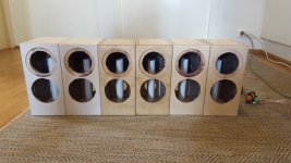
Here are two more pictures about the speakers. With one, you can see the internal structure better. On the other one there's the crossover without the 0,82 Ohm resistor, which I added after listening tests.
A bit how they sound
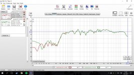
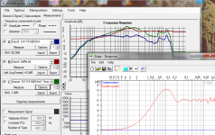
The sound is very nice and pleasant. You can see the FR response in the last post, it was measured in a 5x4m lounge room which connects to several other rooms. The treble is very smooth without any harshness. The treble level is a bit lower than the woofer as I wanted to make it roll off towards high frequencies. Midrange is very clear, especially vocals are excellent to me. The 1-3kHz is a bit elevated, but as a personal preference I let it be that way. Bass could have more oomph below 80Hz (I'm bit of a bass head), but with 4" woofer you get what you order. I chose to tune the cabinet low to get minimal group delay and try to achieve q=0.7 roll-off. It works pretty well, as you get usable in-room response down to 40Hz. The woofer also doesn't easily exceed the xmax unless you listen to a lot of music with 20-30Hz tunes REALLY loud. Overall, no distortion is hearable even if you push them. I could listen to them for hours, and I have. They really deliver.
A bit how they sound
The sound is very nice and pleasant. You can see the FR response in the last post, it was measured in a 5x4m lounge room which connects to several other rooms. The treble is very smooth without any harshness. The treble level is a bit lower than the woofer as I wanted to make it roll off towards high frequencies. Midrange is very clear, especially vocals are excellent to me. The 1-3kHz is a bit elevated, but as a personal preference I let it be that way. Bass could have more oomph below 80Hz (I'm bit of a bass head), but with 4" woofer you get what you order. I chose to tune the cabinet low to get minimal group delay and try to achieve q=0.7 roll-off. It works pretty well, as you get usable in-room response down to 40Hz. The woofer also doesn't easily exceed the xmax unless you listen to a lot of music with 20-30Hz tunes REALLY loud. Overall, no distortion is hearable even if you push them. I could listen to them for hours, and I have. They really deliver.
Attachments
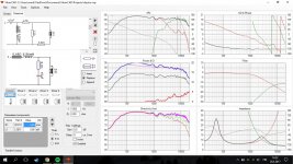
By the graphs posted, it seems you have used the data files downloaded from Dayton...
Dayton Audio DA115-8 4" Aluminum Cone Woofer
These do not account for baffle effects and from the transfer function your sim does not either.
The result is that the real thing is far from measuring as simulated...
Dayton Audio DA115-8 4" Aluminum Cone Woofer
These do not account for baffle effects and from the transfer function your sim does not either.
The result is that the real thing is far from measuring as simulated...
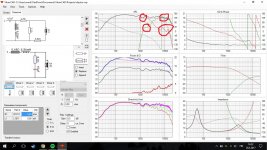
The software I used (VituixCAD) has baffle step simulation function and an enclosure simulation as well, but currently no way of adding the simulated baffle step or enclosure response to the graphs you see on the picture. The baffle step was accounted for with the 0,65mH coil on the woofer, which also works as the low-pass. It isn't full -6db baffle step, because the speakers are used on TV counters etc which are usually straight next to a wall. The measurements reflect this, as they are taken inside the untreated lounge room the speakers are being used at.
I agree with you on that It would have been better to measure the drivers in the enclosures and start the crossover design from that. Instead I opted for making a plan that was likely to work and made the final little tweaks and changes to the crossover along with listening and measurements. This was mostly because the shipping cost of the components are very high compared to their value, so I wanted to order the full batch (drivers and components) at once.
It would have been better to measure the drivers in the enclosures and start the crossover design from that. Instead I opted for making a plan that was likely to work and made the final little tweaks and changes to the crossover along with listening and measurements. This was mostly because the shipping cost of the components are very high compared to their value, so I wanted to order the full batch (drivers and components) at once.This was mostly because the shipping cost of the components are very high compared to their value, so I wanted to order the full batch (drivers and components) at once.
Ha, sadly gone are the good old days of the shop next door...

Btw, it is also possible to add the baffle response to the FRD file supplied.
In The Edge simulate the baffle response and export to txt file.
In HolmImpulse:
1º Load import in A the frd supllied by Dayton.
2º Load import in B the baffle response.
3º Convolve to C= A*B
4º Export the response for use in the xover simulator.
In The Edge simulate the baffle response and export to txt file.
In HolmImpulse:
1º Load import in A the frd supllied by Dayton.
2º Load import in B the baffle response.
3º Convolve to C= A*B
4º Export the response for use in the xover simulator.
Attachments
Design of box is maybe nice.. but this is electronics, not carpenters forum..Nice design Mayuri!
XO design is very bad, this illustrated guide is explicit example for beginners of mistakes which should not make..
Attachments
I tried and I'm 100% sure..So do you think a steeper order XO would have been the crucial difference?
Practically, with this XO there is no point where tweeter works 'alone'..
Diyers think that with cheap drivers they can use low cost XO, in most cases it is just opposite..
The da115 has a cone breakup that really needs to be addressed. This is what is causing the spike beyond your crossover point. A simple solution is to add a small value cap in parallel with the woofers inductor. Typically this will be in the .22 to .47 range. The tweeter would also benefit in using a 3rd order electrical filter. This will dampen the knee and reduce the resonance below the crossover. Other benifits t will be better phase alignment and reduced or eliminated sybalince in the woofer.
Member
Joined 2009
Paid Member
reduced or eliminated sybalince in the woofer.
what is the cause of the sibillance and why does your suggestion improve it - I'm very interested in this as I often find sibillance an issue.
A simple solution is to add a small value cap in parallel with the woofers inductor. Typically this will be in the .22 to .47 range..
With 6R8-8R2-10R resistor..
Also, after inductance he can try with smaller resistor than 8R2, and maybe biger cap..
The tweeter would also benefit in using a 3rd order electrical filter.
Agree..
The breakup is a"ringing" of the aluminum cone. The cap drops that breakup significantly putting it well below (-30db at least) audible range.what is the cause of the sibillance and why does your suggestion improve it - I'm very interested in this as I often find sibillance an issue.
With 6R8-8R2-10R resistor..
Also, after inductance he can try with smaller resistor than 8R2, and maybe biger cap..
..
I have not found the additional resistance necessary unless there is something really wonky with the impedance in which case that needs to be addressed first. I have not had any ultra sonic irregularities by not including one. A larger cap will decrease fc, but not reduce cone breakup enough. If there is already good phase alignment, a larger cap will effect that in addition to increasing the knee before roll off.
The da115 has a cone breakup that really needs to be addressed. This is what is causing the spike beyond your crossover point. A simple solution is to add a small value cap in parallel with the woofers inductor. Typically this will be in the .22 to .47 range. The tweeter would also benefit in using a 3rd order electrical filter. This will dampen the knee and reduce the resonance below the crossover. Other benifits t will be better phase alignment and reduced or eliminated sybalince in the woofer.
The cap to the woofer seems like a handy trick worth trying, and I have 0,22uF caps at hand. Simulation also show this works well. I'll test this when I'm near the speakers again
I am finally near the speakers to try the 0,22uF capacitor trick. No measurements yet, next weekend I'll do proper horizontal plane measurements outdoors.
The treble seems better with this, I think I'll adapt this for the two pairs I still have near me. The remaining 3 pairs are already with their owners Thank you for the input!
The treble seems better with this, I think I'll adapt this for the two pairs I still have near me. The remaining 3 pairs are already with their owners
Thank you for the input!
Last edited:
- Status
- This old topic is closed. If you want to reopen this topic, contact a moderator using the "Report Post" button.
- Home
- Loudspeakers
- Multi-Way
- Dayton Mini Monitor (illustrated guide)