Happy Thanksgiving ! ! !
Yes, you should.
The one major issue that the Ohm F's had was with the voice coil/efficiency. The original spiders are MUCH too soft and allow the weight of the cone to pull the VC out of alignment , very much reducing the motor strength. This was supposedly an issue even when the speakers were first introduced. Simple solution ? Re-spider them with a newer , stiffer Pro Sound unit.
The other half of the problem is the Impedence of the VC. Supposedly this could also be remedied by replacement with a Pro sound unit.
I can't seem to remember the specifics, I'll have to dig up some papers. The gentleman I talked to about this says that after installing the new spider and 8 ohm VC , the driver is about 96 db efficient, and obviously much more dynamic.
I will try to look up which spider and VC he recommended.
Even with their shortcomings, the F's make music like no other drivers/speakers I've ever heard. Granted I haven't heard alot of the most current designs, but I've definitely heard some very fine sounding and well regarded speakers.
Have a good one...............................Nihilist
It has been a long time since i heard the Ohm F... at the time i felt it had real potential, but some shortcomings i couldn't live with.
I have heard the DDD version of the Walsh recently and really liked them. Very expensive thou.
A friend just replaced his Ohm Fs with a set of FE127e in a set of PAWOs and finds them overall more satisfying (granted that has something to do with his available amplifiers)
dave
I have heard the DDD version of the Walsh recently and really liked them. Very expensive thou.
A friend just replaced his Ohm Fs with a set of FE127e in a set of PAWOs and finds them overall more satisfying (granted that has something to do with his available amplifiers)
dave
Hi mamboni,
If you do find the time to post some more information about your modification I would really be interested.
I'm experimenting with woofers / wide range drivers crossed to tweeters at the moment, but I hadn't even thought about woofer cone modification.
Best regards,
Andrew.
If you do find the time to post some more information about your modification I would really be interested.
I'm experimenting with woofers / wide range drivers crossed to tweeters at the moment, but I hadn't even thought about woofer cone modification.
Best regards,
Andrew.
puzzlecoat, & ductseal are your friends... and i'm just starting to play with damar for hilites...
http://www.t-linespeakers.org/design/tweeks.html
dave
http://www.t-linespeakers.org/design/tweeks.html
dave
OK - give me a day to put together the particulars on the design, and I'l try to post some photographs.
I wanted to just add that the quality of source material and amplification is very important for optimizing the performance of the Walsh 5 Series 3 loudspeakers - they are extremely revealing. Also, though these loudspeakers, my well-recorded CDs sound wonderful, while the not-well-recorded CDs sound worse than ever.
My system:
RJ-Tech DVX DVD player
Pioneer Elite SP-99D Preamplifier-Processor
Sumo Andromeda II Mosfet Stereo Power Amplifier
Interconnects: Kimber (entry-level stuff)
Loudspeaker cables: 18 AWG .9999 solid-conductor silver teflon-coated, 12' run, bare wire connections
Panamax line conditioner/protection
Significant improvements in sound were noted when I replaced by Rotel preamp with the Pioneer unit - the midrange was hugely opened up. The Sumo amp sweet yet powerful (240W into 8 ohms; 400W into 4 ohms)- a tube amp sound on steroids - nary a hint of solid state grunge - incredibly smooth and correct midrange and treble, string partials done right, cymbals now sound like cymbals. The RJ-Tech DVD blows any CD players I've used, mainly Rotels, out of the water.
One last thing which really surprised me - effect of speaker cabling. I had been using large braided pure copper speaker cables from MonsterCable, and found then detailed if bright and a bit brittle - the high treble still made me winch at times. On a hunch, I switched to a 12 foot solid core pure silver cable (teflon coated - looks line thin spaghetti)....holy smokes!!!! I'd always thought cable proponents mostly full-of-it, that a cable was just resistance, inductance and capacitance in parallel and all the cable had to do was keep all three, especially the reactive components, as low as possible. But, the silver cable just knocked my socks off! The sound coming out of the Walshs was just gorgious! Most obvious improvement was to the very top octaves, the highest partials of the cymbals, bells and high strings. Now I could hear the myriad overtones, all of them all, in all their rarified glory, clearly and delicately. All traces of phase shift and coarseness are gone. Cymbal crashes that before sounded like air hissing now sounded like...cymbals, shimmering and ephemeral. Folks, I urge to pick up some 18g solid silver teflon-coated speaker wire and try it - you will be amazed.
Build your own Walsh loudspeaker
Build your own Walsh loudspeaker for about $250 in parts and materials:
Woofer: PIONEER W25GR31-51F 10" BUTYL SURR WOOFER (http://www.partsexpress.com/pe/showdetl.cfm?&Partnumber=290-088)
Tweeter: TANG BAND 28-847SA SHIELDED NEODYMIUM DOME TWEETER
http://www.partsexpress.com/pe/showdetl.cfm?&Partnumber=264-822
6.8 uf high pass capacitor (metalized polypropylene) to tweeter (http://www.partsexpress.com/pe/pshowdetl.cfm?&PartNumber=027-427)
4 ohm power resistor in tweeter circuit.
Sonotube: nominal dia. = 12.5 inch height = 37 inch
Stuffing: acoustastuff ~50% of internal volume
SPEAKER REPAIR GLUE 1 oz. BOTTLE http://www.partsexpress.com/pe/showdetl.cfm?&Partnumber=340-076
This speaker glue has consistency of Elmer’s glue when wet, dries fairly quickly (water base) to form a clear and very flexible soft clear rubber with excellent damping characteristics.
Walsh Loudspeaker: two-way X-over first order (6dB/oct) high pass filter to tweeter at 8 kHz
Woofer – full range (no crossover)
Alignment: Acoustic suspension (Vb=2.5 cu. Ft; Qtc = .816; Fc = 49 Hz (-3dB))
Frequency Response: 49 - 20,000 Hertz (-3 db, +0db)
SPL: 89 dB/watt Max Power: ~100W
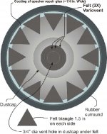
Illustration: Cone with felt damping applied with speaker repair glue.
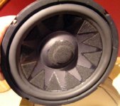
Photos #1(schematic) and #2: woofer with felt dampers and felt variovent in dustcap. Variovent consists of ¾” dia. Hole cut into center of dustcap and hole covered with three laters of felt to provide resistive vent.
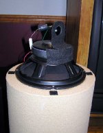
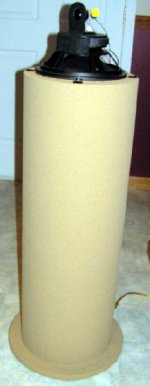
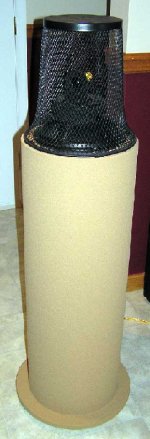
Photos 3-5: final loudspeaker.
Build your own Walsh loudspeaker for about $250 in parts and materials:
Woofer: PIONEER W25GR31-51F 10" BUTYL SURR WOOFER (http://www.partsexpress.com/pe/showdetl.cfm?&Partnumber=290-088)
Tweeter: TANG BAND 28-847SA SHIELDED NEODYMIUM DOME TWEETER
http://www.partsexpress.com/pe/showdetl.cfm?&Partnumber=264-822
6.8 uf high pass capacitor (metalized polypropylene) to tweeter (http://www.partsexpress.com/pe/pshowdetl.cfm?&PartNumber=027-427)
4 ohm power resistor in tweeter circuit.
Sonotube: nominal dia. = 12.5 inch height = 37 inch
Stuffing: acoustastuff ~50% of internal volume
SPEAKER REPAIR GLUE 1 oz. BOTTLE http://www.partsexpress.com/pe/showdetl.cfm?&Partnumber=340-076
This speaker glue has consistency of Elmer’s glue when wet, dries fairly quickly (water base) to form a clear and very flexible soft clear rubber with excellent damping characteristics.
Walsh Loudspeaker: two-way X-over first order (6dB/oct) high pass filter to tweeter at 8 kHz
Woofer – full range (no crossover)
Alignment: Acoustic suspension (Vb=2.5 cu. Ft; Qtc = .816; Fc = 49 Hz (-3dB))
Frequency Response: 49 - 20,000 Hertz (-3 db, +0db)
SPL: 89 dB/watt Max Power: ~100W
Illustration: Cone with felt damping applied with speaker repair glue.
Photos #1(schematic) and #2: woofer with felt dampers and felt variovent in dustcap. Variovent consists of ¾” dia. Hole cut into center of dustcap and hole covered with three laters of felt to provide resistive vent.
Photos 3-5: final loudspeaker.
Ohm model D
Years ago-circa 1970, I had these bookshelf Ohm model "d"; I believe they were 2 way paper tweeter with 8". The magnet on the 8" was square alnico with the open ends capped.
These made a distinctive bass when played loud, have not heard that again untill this day. Wish I had a nos pair. I blew the surrounds out and they ended up at the local landfill. The power amp was a Lafette lr1500ta receiver.
cheers
")
Years ago-circa 1970, I had these bookshelf Ohm model "d"; I believe they were 2 way paper tweeter with 8". The magnet on the 8" was square alnico with the open ends capped.
These made a distinctive bass when played loud, have not heard that again untill this day. Wish I had a nos pair. I blew the surrounds out and they ended up at the local landfill. The power amp was a Lafette lr1500ta receiver.
cheers
I am certain that a 6.5 inch woofer would work very well using analogous cone modifications and architecture. Of course, a 6.5 in woofer will not go as low, be as efficient and go as loud as a 10 inch woofer, all other things being equal - there's the rub.
You would want to use a reflex (ported) design to extend bass output (unless you have a subwoofer). The ideal 6.5 inch woofer would have:
Lowest possible free air resonance
Low Qts, say 0.35 or less
Very low voice coil inductance
Extended high frequency response
As to the latter, I like paper cones over all other as they represent both excellent value and in fact are only slightly improved upon by expensive exotics like kevlar and impregnates. The paper cones provide excellent combination of low mass and reasonable internal damping - but cone resonance remains a major problem unless either the crossover point is set below the cone resonance (which of course obviates all the advantages of a Walsh operation, the intent being to the utilize the 'bending' cone's sound production but manage the resonance), or the cone mods I've outlined upon are applied.
I've listed the component drives and sundry supplies and parts. Instructions on construction are not needed - the design is the model of simplicity and the photos should make their building self-explanatory. Excepting for possibly the finishing work, these loudspeakers can easily be constructed in a day. You will be rewarded with an exceptionally clean and coherent-sounding loudspeaker which images and soundstages like no other, all for a few hours of work and a couple of hundred dollars.
I don't have detailed instructions. Let me describe the construct as it is the model of simplicity.
This is a closed box (acoustic suspension) alignment as dictated by the specific 10" woofer being utilized, the Pioneer driver part listed in a prior posting. The exact cabinet volume is not critical - the target is about 2.4 cu ft, which should yield a system Q of 0.7 - 0.8.
The cabinet is made of a 36" long 12" internal diameter sonotube which can be purchased at Home Depot or Lowes. For each sonotube, three circular pieces are cut out of a 4' x 2' sheet of 3/4" thick particleboard. Two are circles approx 12" in outer diameter cut to fit snugly inside the tube - each of these has a center hole cut into it of 9 1/8" diameter. One is glued into the sonotube interior at it's midpoint to provide rigidity. The second is glued to the end of the tube flush with the cut end - the woofer will ultimately be mounted onto this top-piece centered on the 9.125" opening. For the bottom of the sonotube, I chose a circular diameter, obviously solid, particle board cutout of 16" diameter.
The completed cabinets (drivers not installed yet) need only to be wired and stuffed. Any good quality 18g or 16g OFC wire will do. I installed the binding posts in the bottom 16" piece facing up on the flange. Holes are drilled so the wires can be run through then bottom piece and under it and back into the interior of the cabinet then up the the drivers. Two holes are drilled through the top piece behind where the woofer driver will sit.
Acoustastuff is added to 50% fill. The cabinets can be finished to taste: wood venier or textured paint as I did. Once the finish work is done, bottom spikes can be installed in the 16" bottom piece close to the outer edges.
Before installing the woofers, I cut gaskets out of 1/8
" thick cork sheet (available at Lowes) having 9.125" inner dia. and 10.5" outer diameter and glued to the top piece around the center opening (this damps the woofer metal basket vibrations). All wire holes are hot glued to make them air tight.
The woofers have at this point have had the felt damping triangles affixed to the paper cone as per my drawings and photo above using the glue specified [important as it dries flexible with excellent viscoelastic damping properties]( see earlier post). The dust cap mod consists of carefully cutting a 1/2" diameter hole in the center of the dust cap and them covering it with three circular sections of felt cloth as shown above - this acts as a variovent, largely eliminates duct cap resonance and greatly improves the upper midrange.
The woofers are screwed into place flush on the cork gasket and perfectly centered over the 9 1/4" cabinet opening. The wires are soldiered to the woofer, red to positive (important to observe polarity).
The tweeter is a 1 inch soft dome from Tagband, crossed over using a 5.5 microfarad high quality polypropylene cap in series with a 4 ohm power resistor (5-10W). As the tweeter is nominal 4 ohms, this should provide for a first order high pass slope with -3dB point at about 8 khz. That's all there is in terms of crossover - the woofer is wired directly and is run full range. Important: the tweeter polarity is wired positive tweeter terminal to positive woofer terminal (so in fact, as the woofer is firing down into the cabinet, the woofer is actually 180 degrees out of phase with the tweeter. Based on listening, this wiring sounds superior. I believe that the signal experiences approx 180 phase rotation across the bandwidth of the woofer so that at the crossover point of 8 khz the woofer and tweeter are ostensibly phase aligned).
The tweeter is attached to the top of the woofer pole piece so as not to obstruct the woofer's pole vent. The tweeter voice coil should be at the acoustic center of the woofer voice coil [in the vertical axis] so the drivers are time aligned. I used a 3" section of 1/2 " aluminum angle, epoxyed to the pole piece; then I glued the flange of the tweeter to the front surface of the vertical element of the aluminum angle. The tweeter thus is oriented with the flange in the vertical and it's voice coil centered above the woofer pole vent opening. The flange of the tweeter and the adjacent front top of the woofer magnet surface is then covered with felt to provide cosmetic uniformity and eliminate baffle diffraction.
The speakers are positioned so that the tweeters are toed in at 45 degrees and pointing into the center of the room. The tweeter axes cross well in from the the listener. The resulting sweetspot is extremely broad, so that many listeners will enjoy an equally excellent spacious soundstage with holographic imaging.
The speakers produce an exceptionally coherent and clean sound (vocal reproduction is outstanding) that is substantially omnidirectional until crossover when the sound radiation becomes progressively directional above 8 khz (approx. wavelength 1.25 inch over a 3 inch diameter tweeter baffle). This results in outstanding image localization.
The speakers can play extremely loud (over 100 dB) cleanly and without strain amd require no more than 100W of clean power. The speakers a very easy resistive load to the amplifier. The bass is tight and tuneful and in room one should achieve usable output easily to 40 hz. (anechoic about 49Hz - but closed box enjoys gradual rolloff below resonance and benefits greatly from room reinforcement).
If necessary, I can post some photos if you are unsure about a particular part of the assembly.
Ohm Walsh by mamboni
Yes, pictures of how the tweeter is attached to the woofer would be helpful and also pictures of where you place the crossover components. Basically any pictures showing the process would be helpful but what I have listed above would be a start.
Thanks.
Yes, pictures of how the tweeter is attached to the woofer would be helpful and also pictures of where you place the crossover components. Basically any pictures showing the process would be helpful but what I have listed above would be a start.
Thanks.
- Status
- This old topic is closed. If you want to reopen this topic, contact a moderator using the "Report Post" button.
- Home
- Loudspeakers
- Multi-Way
- OHM Acoustics "Walsh F" Speaker remakes