Thijs666,I still have to make that adapter for REW to be able to use a loopback as timing reference. I hope that will clear up the questions I have regarding the strange phase drop that occurs on axis around the xover point, but doesn't happen 10 cm off axis.
You state the "strange phase drop doesn't happen 10 cm off axis" which indicates you may be taking your measurements at the mouth of the horn, which will not result in the phase or frequency response that the cabinet will exhibit at two or more meters distance.
To accurately measure the on and off axis response making a "turntable" which rotates from the apex of the horn throat would be advised.
The combined raw response of the SynTripP 2x10" and 3" diaphragm HF was nearly flat in phase response over several octaves either side of the acoustical crossover region.
Cheers,
Art
It doesn't let me zoom in any further, even when I try like you said. It doesn't go under 1 ms for the full window. Maybe it's my measurement? Sweep length was 128k, the shortest REW allows.
I did some new measurements with a longer sweep length, but I still cannot zoom in any further
 . I did manage to use REW's loopback as timing reference option. But that didn't improve the phase measurements. If anything, it made it worse, because the signal went through the DCX and then a class D amp. REW gave a delay of 1.7 or so meters while the mic was at 1 meter and 0.77 meter with the mic right in front of the horn. Still the phase curve is all over the place... Does anyone have a suggestion? What am I doing wrong here??
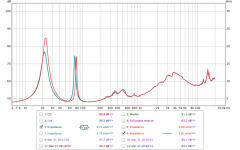
I did enlarge the vent holes also. Made them more than double the size. Tuning went up a little bit, but not as much as I had hoped (see impedance and SPL graphs).
Attachments
Correct. I did that because it results in a much flatter phase response. The phase response worsens the farther away I move the mic from the horn.Thijs666,
You state the "strange phase drop doesn't happen 10 cm off axis" which indicates you may be taking your measurements at the mouth of the horn
Exactly!, which will not result in the phase or frequency response that the cabinet will exhibit at two or more meters distance.
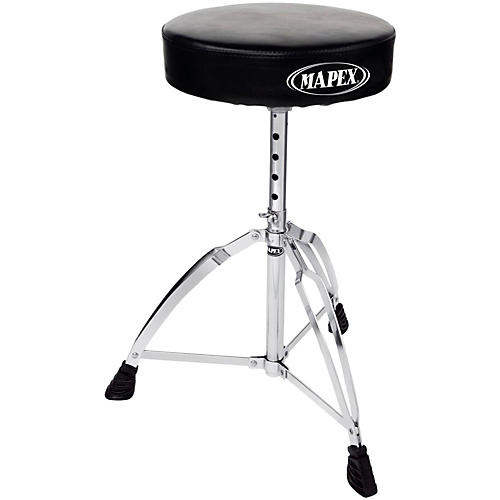
A simple drum throne would be a quick and easy solution, of which I have several. For non drummers: the seat turns freelyTo accurately measure the on and off axis response making a "turntable" which rotates from the apex of the horn throat would be advised.
.
Just to be clear: Are you saying that the phase response should be more or less flat at any distance from the horn mouth?The combined raw response of the SynTripP 2x10" and 3" diaphragm HF was nearly flat in phase response over several octaves either side of the acoustical crossover region.
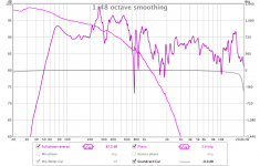
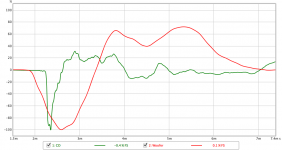
Maybe I should try different measurement software? With REW the phase response just goes all over the place if there is a delay. I mean, the pink curve is taken with the mic right in front of the horn (at '0 meters') and the only difference with the green curve is that I have the loopback as timing reference option enabled, which displays the delay of the DCX2496 AD/DA conversion... (note the scales on the right)
Attachments
Another way to deal with phase is to make three measurements -- woofers only, tweeter only and both playing together (all without crossovers of course, and including phase measurement and measured without moving anything between takes). Import the FRD files into something like Xsim. and simulate the situation of both playing together using the separate measurements. Adjust the delay on the tweeter (in Xsim's "tune" window for it) until the "together" magnitude matches what you measured.... then the relative delay (which is all that matters) is correct. Jeff Bagby has a detailed description of this somewhere probably at the Techtalk forum.
Last edited:
Are you saying that the phase response should be more or less flat
Maybe stating the obvious, but in case not -- the phase response will NEVER be "flat" unless you subtract delay in the graph (and unless what you measure is linear phase)
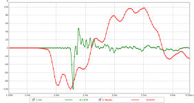
I think you will see nicer looking phase if you set the IR windowing in REW to 5 cycle FDW instead of fractional octave smoothing. Part of all those phase wraps may be due to the room/reflections; especially since you say you get smoother phase when measuring right at the mouth.
Did that...Another way to deal with phase is to make three measurements -- woofers only, tweeter only and both playing together (all without crossovers of course, and including phase measurement and measured without moving anything between takes).
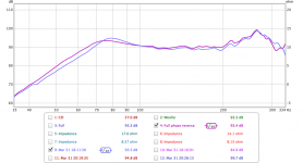
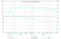
...and that today outside on the roof, speaker pointed upwards. Here are the results. Phase looks much better nownc535 said:I think you will see nicer looking phase if you set the IR windowing in REW to 5 cycle FDW instead of fractional octave smoothing. Part of all those phase wraps may be due to the room/reflections; especially since you say you get smoother phase when measuring right at the mouth.
 .
.Going to try this in a bit... Stay focused.bwaslo said:Import the FRD files into something like Xsim. and simulate the situation of both playing together using the separate measurements. Adjust the delay on the tweeter (in Xsim's "tune" window for it) until the "together" magnitude matches what you measured.... then the relative delay (which is all that matters) is correct.
And thank you guys!!
Also included measurements with and without horn extender. The effect can bee seen clearly: almost 4dB more
Attachments
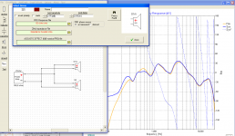
Like this?Import the FRD files into something like Xsim. and simulate the situation of both playing together using the separate measurements. Adjust the delay on the tweeter (in Xsim's "tune" window for it) until the "together" magnitude matches what you measured.... then the relative delay (which is all that matters) is correct.
(Btw, nice little program you wrote! Makes it very easy to mess around with Xover components
)Attachments
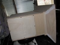
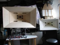
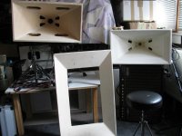
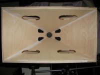
Some pictures to show the current prototype. With and without dixie cup extender. The white Synergy on the right is the one I made with the BMS4550, Visaton M10 and Eminence Beta12 (see my other thread).
Attachments
Like this?
(Btw, nice little program you wrote! Makes it very easy to mess around with Xover components
Yeah, that's basically it. I'd expect the match to be a little closer, though, but in the area where windowing of the IR is used that can get messed up some (windowing isn't a linear math process). The effects of the delay error will be strongest at higher frequencies, so I preferentially optimize for match there like you did.
(what's the 'Dixie cup extender' you're referring to?) edit --- Never mind, I think I see what you mean.
Last edited:
Yes, that was what I was saying, and now you have sorted out the problem, the phase response is more or less flat.Just to be clear: Are you saying that the phase response should be more or less flat at any distance from the horn mouth?
Tricky to keep it flat unless you use FIR filters.
That said, I found that 42 years of swapping between flat phase cue headphones and listening to systems with 2, 3 and 4 way LR 24 dB per octave crossovers, which introduce 360, 720 or 1080 degrees of "phase wrap" (90 degrees per "pole") I find I am insensitive to phase, as long as the transition is smooth.
I have also used flat phase headphones to listen to Merlijn van Veen's recordings which progressively introduce phase wrap on the same musical piece, and can't hear the difference in that controlled environment.
I have never claimed to have golden ears, and now that the golden years are approaching, they ain't getting any better.
Which I would have worn hearing protection during the first 8 years of cabinet building and cutting sheet metal with a circular saw ...
Art
Last edited:


Delay measurements
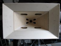
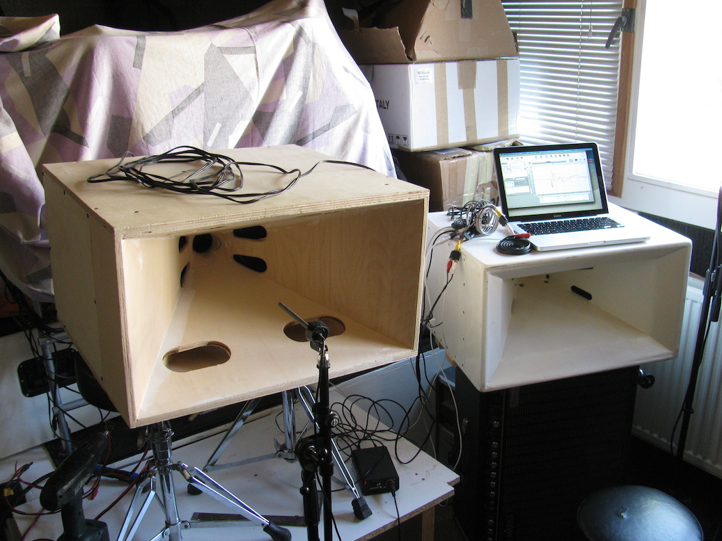
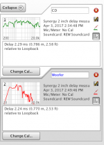
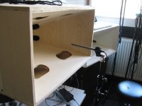
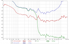
I was still unsure about the delay needed for the CD, so I figured I could specifically measure woofer and CD delay using REW's loopback timing reference... So I did some measurements again using this setup to have as little room influence as possible:

Then I did about 10 consecutive measurements to rule out glitches and other errors. This resulted in the following:
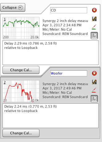
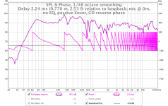
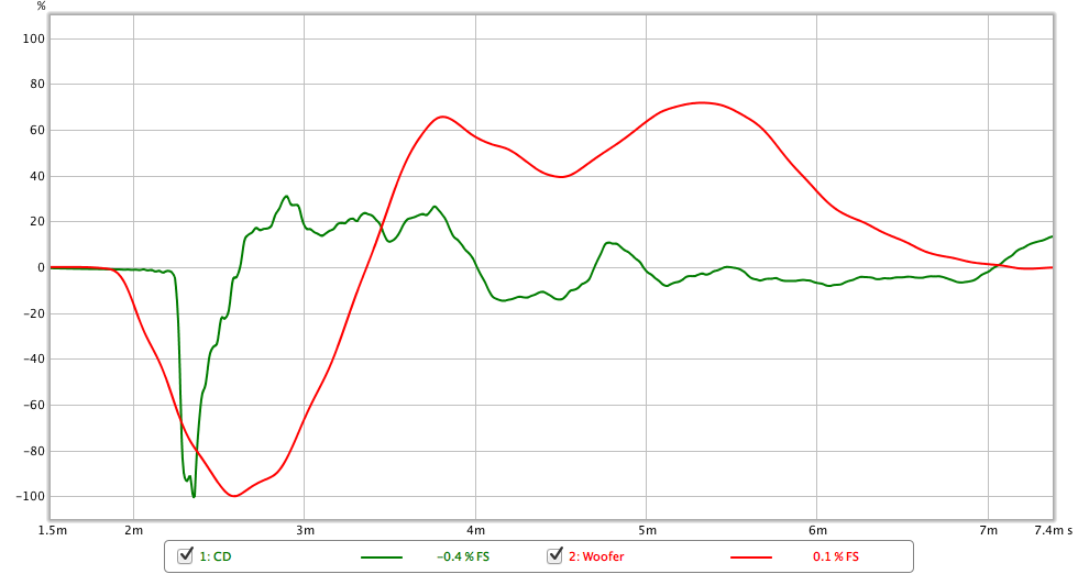
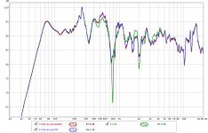
These numbers kept turning up each measurement, so I'm pretty sure they are correct. This means there's only 50 microseconds of path difference, or 1.6 cm, or 0.05 ft, or 0.6 inch. The impulse responses look like this:
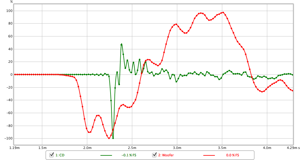
And the step responses look like this:
All measurements were taken without any EQ, delay or crossover (that's why the CD doesn't start at 20 Hz, but at 200 Hz).
So unless my measurement setup (see first two photographs) is wrong, I don't think I would really need to delay the woofer section (yes, the woofer section, no the CD). I've seen that the majority of impulse response charts on this forum have scales in milliseconds, not microseconds, so I guess I'm on the right track here. Can anyone please confirm? This looks a bit to good to be true.
I was still unsure about the delay needed for the CD, so I figured I could specifically measure woofer and CD delay using REW's loopback timing reference... So I did some measurements again using this setup to have as little room influence as possible:
Then I did about 10 consecutive measurements to rule out glitches and other errors. This resulted in the following:
These numbers kept turning up each measurement, so I'm pretty sure they are correct. This means there's only 50 microseconds of path difference, or 1.6 cm, or 0.05 ft, or 0.6 inch. The impulse responses look like this:
And the step responses look like this:
All measurements were taken without any EQ, delay or crossover (that's why the CD doesn't start at 20 Hz, but at 200 Hz).
So unless my measurement setup (see first two photographs) is wrong, I don't think I would really need to delay the woofer section (yes, the woofer section, no the CD). I've seen that the majority of impulse response charts on this forum have scales in milliseconds, not microseconds, so I guess I'm on the right track here. Can anyone please confirm? This looks a bit to good to be true
.Attachments

If it looks too good to be true, it usually is as I've found out to my embarrassment a couple of times.
As I may have mentioned before, with minimum phase filters you align the drivers such that the starting points of their IRs are aligned. My eyes say the IRs in your measurement are about .4 ms off. Your woofer apparently has a high BW so when you align starts of IRs, the entire leading edges of the IRs will be just about coincident. You are fortunate with these IRs that have no pre-ringing, the starting points are easy to determine.
Ultimately, you need to do the measurement with the XO filters in place but only one driver at a time powered. Given you are using passives, you may need to substitute a dummy load for the un-driven driver. The reason for this is that the filters have different delays and thus affect the time alignment. The differential filter delays can compensate for a path length difference.
Delay measurements with Xover
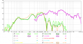
These are per driver with the prototype Xover in place, substituting a load for the non-connected driver, overlayed in REW...
Impulse response:
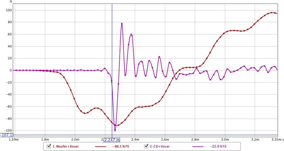
Step response:
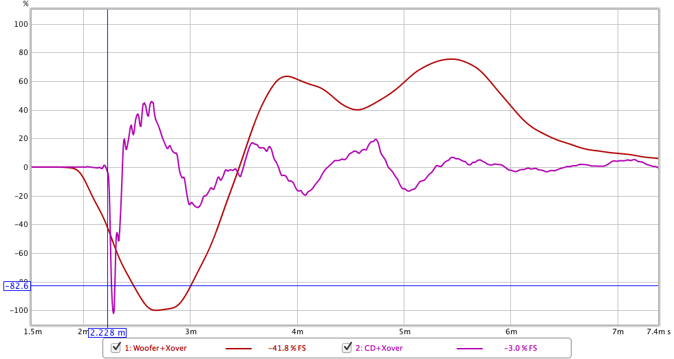
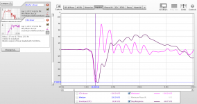
REW screen:
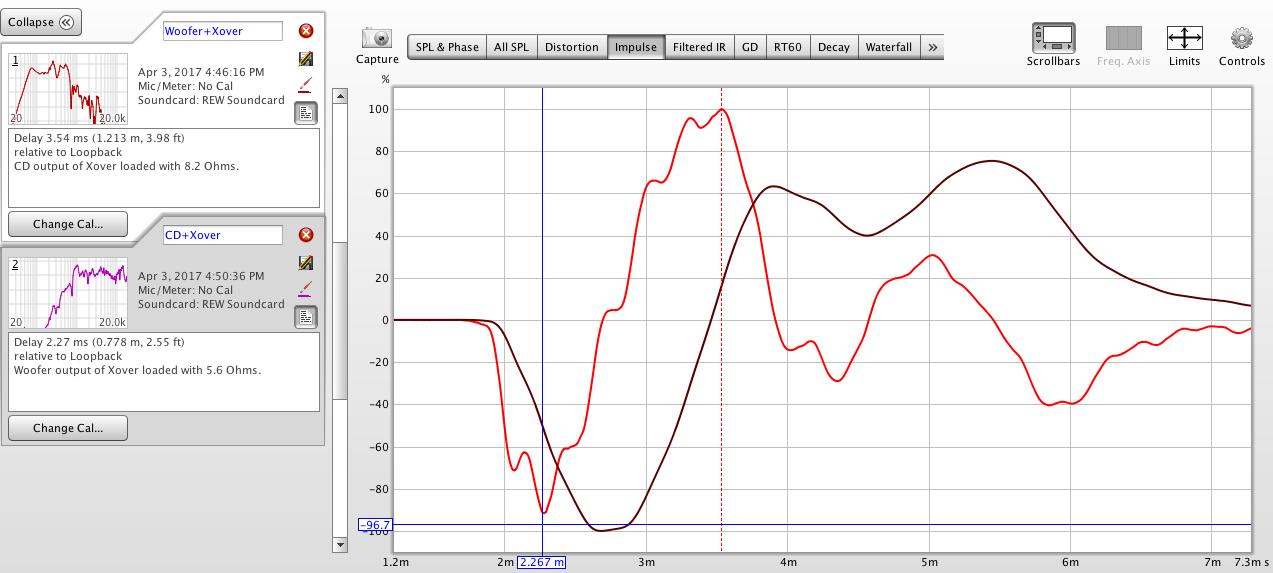
The woofer delay calculated by REW (vertical red dotted line) is obviously incorrect. I placed the cursor at where I think it should be: 2.267 ms. That's (almost) exactly the delay of the CD...
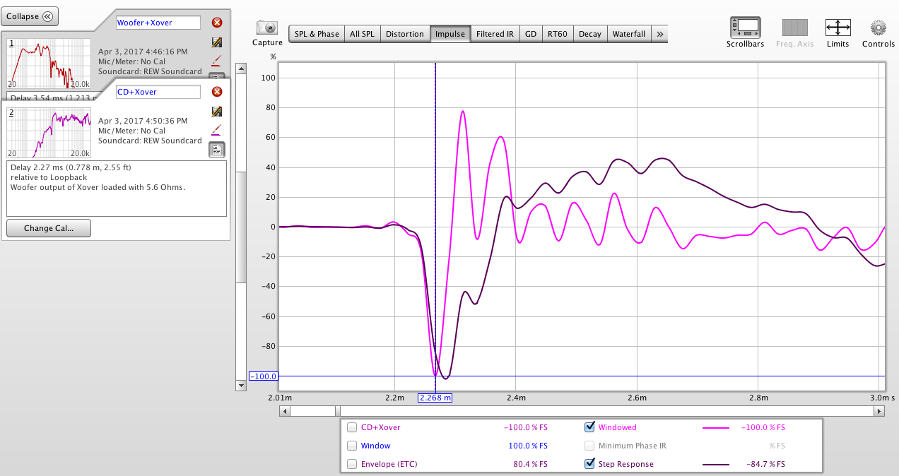
From the step response, there's still 0.4 ms between the start of the response, the peaks are time aligned. Who thinks that should be corrected?
The prototype doesn't sound bad at all, on the contrary.
These are per driver with the prototype Xover in place, substituting a load for the non-connected driver, overlayed in REW...
Impulse response:
Step response:
REW screen:
The woofer delay calculated by REW (vertical red dotted line) is obviously incorrect. I placed the cursor at where I think it should be: 2.267 ms. That's (almost) exactly the delay of the CD...
From the step response, there's still 0.4 ms between the start of the response, the peaks are time aligned. Who thinks that should be corrected?
The prototype doesn't sound bad at all, on the contrary
.Attachments


Why not measure with the crossover in place and look at the phase response through the crossover? If there is a jump in the response then there is a delay there. Remember that high-pass and low-pass filters also add their own delay. Getting these impulse responses exactly aligned means little in the final design. What you are really looking for is a smooth phase response through the crossover.
Why not measure with the crossover in place and look at the phase response through the crossover? If there is a jump in the response then there is a delay there.
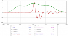
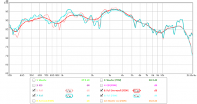
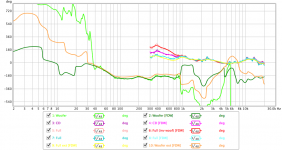
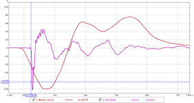
Thank you for the suggestion. Using the same measurement setup, this results in the following phase response, using various crossover configurations (woofer inverted, 'normal' and CD inverted):
Looks like one of them definitely needs the be connected inverted. The green curve (both drivers connected 'normally') shows a big jump in phase.
But the SPL curve shows a big dip from 700-900 Hz, so the crossover still needs some tweaking :s.
Attachments
Looks like both drivers connected to same polarity results in significant delay. Ditch that option. Reversed polarity for one driver is the way to go.
From the measurements, is your crossover somewhere in the 700-1k region? That would correspond to the little dip and peak in that region in the blue plot of the phase curve. You can calculate the approximate delay by knowing the jump in phase.
1 cycle at 700 Hz =700 cycles/second
Or, 360 degrees at 700 Hz = 1/700 seconds = 1.43 ms, i.e., it takes 1.43 ms for one complete cycle of 700 Hz.
So, for example, if you want to shift the phase by 50 degrees, delay = 1.43 x 50/360 ms
What would also help is if you plotted individual driver responses with crossover so that you can see the phase overlap through the crossover.
This thread is an excellent example of how it should be done:
Crossover mods for the AR4x - Mods, Tweaks, and Upgrades to the Classics - The Classic Speaker Pages Discussion Forums
If there is not good phase overlap through the crossover, then you can get peaks and dips at neighboring frequencies, and also at different angles.
- Status
- This old topic is closed. If you want to reopen this topic, contact a moderator using the "Report Post" button.
- Home
- Loudspeakers
- Multi-Way
- Synergy horn for 135 dB+