Hi!
I'm a regular lurker around these forums, but I very rarely post, since i haven't gotten around to building much myself.
Anyway, recently i started to put an idea i have into a couple of prototypes, just to try things out. I'm doing a mid/tweeter box with time alignment. What i wan't to do is to make a recessed, padded cone for the tweeter to avoid edge diffraction as much as possible.
I know it's a bit crazy for a first project, but i'm not scared of messing up, that's the best way to learn.
The tweeter is a Peerless DT 100 wide angle face plate.
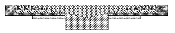
I'm trying to get the cone angle as close to the face plate angle as possible, not to screw up the drivers response. I'm including a drawing to show what i had in mind.
 Does this make any sense at all to you guys?
The foam for the cone is this stuff
here (with the foil ripped off).
It's got adhevise on the back, and the foil is easy to peel.
I'm going to measure the rig when i'm done, to see what this does to frequency response, i'm hoping it will be good .
.
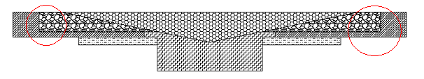
What i'm concerned with is if the straight angle in the wood will make diffraction really messy, or if the foam will take care of this?
(XO will be around 2-3Khz, haven't decided yet)
Also, is horn loading going to be an issue with the low angle (~11,5 degrees)?
So the question is, will it float?
I'm just a newbie so i'll gladly take any advice i can get.
Best regards
Andreas
I'm a regular lurker around these forums, but I very rarely post, since i haven't gotten around to building much myself.
Anyway, recently i started to put an idea i have into a couple of prototypes, just to try things out. I'm doing a mid/tweeter box with time alignment. What i wan't to do is to make a recessed, padded cone for the tweeter to avoid edge diffraction as much as possible.
I know it's a bit crazy for a first project, but i'm not scared of messing up, that's the best way to learn.
The tweeter is a Peerless DT 100 wide angle face plate.
I'm trying to get the cone angle as close to the face plate angle as possible, not to screw up the drivers response. I'm including a drawing to show what i had in mind.
Does this make any sense at all to you guys?The foam for the cone is this stuff
here (with the foil ripped off).
It's got adhevise on the back, and the foil is easy to peel.
I'm going to measure the rig when i'm done, to see what this does to frequency response, i'm hoping it will be good
. What i'm concerned with is if the straight angle in the wood will make diffraction really messy, or if the foam will take care of this?
(XO will be around 2-3Khz, haven't decided yet)
Also, is horn loading going to be an issue with the low angle (~11,5 degrees)?
So the question is, will it float?
I'm just a newbie so i'll gladly take any advice i can get.
Best regards
Andreas
Attachments
Hmm, I am not quite sure what each different pattern is in your drawing so I will just say that I have made conical flare horns to recess a tweeter to get physical alignment and to control off-axis response a bit. I did not line the horn with damping material, but I did add a foam or felt ring around the mouth to attenuate mouth reflections.
Regardless, the type of foam you linked to, 'rebond' (used as carpet padding or for packaging, at least in the USA), isn't really suitable since it has a variable density due to the different density foam pieces used and the glue to bind them all together.
GM
Regardless, the type of foam you linked to, 'rebond' (used as carpet padding or for packaging, at least in the USA), isn't really suitable since it has a variable density due to the different density foam pieces used and the glue to bind them all together.
GM
Hi GM, thanks for the reply!
Sorry, i was getting sleepy when i posted this, i should've explained the picture better.
The thing in the middle bottom is the driver, top middle is the far side of the foam cone. Left and right of this are the foam slopes (it's one big slab of foam, but it's a cross-section).
The angled pieces are 19mm particle board and the piece surrounding the driver is plywood, for reinforcement.
The wood parts may become a little weak as i've pictured them, i'll probably use more steps in the cutout to make it stronger, the thin parts are only about 4mm in the picture.
The foam is cheap stuff for the protoypes, i'll probably exchange it for something else when i do some real speakers.
(Besides, i tried to dye it black, but the colour wouldn't take very well.)
Do you think the foam would be good enough for damping inside the cabinet (it comes in 1, 2 and 3 cm thickness)?
To cut the angle in the foam i'm going to try hot wire mounted from the center, pulling it around the edge of the cutout.
Maybe i'll have to rough up the surface afterwards, i don't want the cells in the foam to melt shut.
This is the best i could come up with for cutting, does anyone have any other idea how to do it?
regards
Andreas
Hi sreten!
So you're saying to scrap the foam altogether and just do the cone in particleboard, and round off the edges of the cone?
Or just make the solid section the same shape as the cone, offset, avoiding the sharp edges?
The problem is i don't really know how to do either...
I have a router, but the angled bits are all 45 degrees, so they wont help much.
The best thing i can come up with is to route lots of stepped concentric circles in the approximate angle, and then sand them down so they make a flat surface.
Maybe it's time to make one of those Jasper rigs, that'd make the whole thing alot easier. Still have to sand it thou...
Would it be pointless to make the cone offset and add foam lining, compared to making it lined up with the faceplate angle, with no foam?
There's not much extra work to make it offset, and i'm kinda curious to how it would turn out. I think i'll do both, measure them and compare the results.
I have an extra peice the right size for the baffle, so i'll do one third baffle the same as the best of the other two, to make the pair match.
I'll keep you posted on any progress (if any) i make.
I just can't seem to let go of the foam idea...
regards
Andreas
nuppe said:Hi sreten!
The best thing i can come up with is to route lots of stepped concentric circles in the approximate angle, and then sand them down so they make a flat surface.
regards
Andreas
Using filler between each edge before you
start sanding should make life a lot easier.
sreten.Thanks Sreten!
That really is some good advice.
I would probably just have sanded till i dropped if you hadn't said something!
I've spent the afternoon making myself an improvised, adjustable circle cutting jig. It's not done yet, but when it is i'll post a picture.
It's kinda like a jasper jig, but instead of all the holes i'm using a center pin on a piece of wood sliding along a channel.
Can't wait to try it out...
Then i'll have my cone in no time.
Well, minus one half day making the jig...
regards
Andreas
Hi,
From what I understand the idea is to time align the driver units in such a way as to create either a line source or point source without the aid of electronic time alignment/delay techniques.
The foam lining is just to avoid secondary reflections from the baffle itself.
Cheers,
If you really want to try & align the drivers visually
From what I understand the idea is to time align the driver units in such a way as to create either a line source or point source without the aid of electronic time alignment/delay techniques.
The foam lining is just to avoid secondary reflections from the baffle itself.
Cheers,
Yes, Frank is spot on.
From what i've heard, the acoustic centers varies with frequency, so the best you get is an approximation. My drivers will be aligned so that the top point on the dome of the tweeter is in the same plane as the bottom of the cone of the mid. I've read recommendations to align the pole pieces, but that would make my cone one cm deeper, and a lot wider, so this is a tradeoff.
These are prototyes for a three way, but i haven't bothered about time aligning the bass, the difference relative to frequency at crossover (200-300 Hz) is small.
Besides, it would be a real hassle to do the same with the mid, that would be one large baffle...
regards
Andreas
Just a thought. . . Yes, the acoustic center of a driver varies with frequency. There is little you can do about this. Yet, at the crossover frequency you can match the acoustic centers of the drivers. This way you will have a smooth transient transition. The only way to determine the acoustic center at crossover frequency is to measure it. The acoustic center of the drivers must be determined as part of the crossover design. If, at a later time, you change the crossover frequency or slopes, the acoustic centers will change.
If you are using impulse testing (assuming a postive going impulse input to loudspeaker under testing, polarity conservation, and the crossover network already close to summing), a good rule of thumb for determing acoustic center at crossover is to match first negative going spike of the tweeter with the peak of the first positive going spike of the woofer. The improvement in sound quality of transiently aligned and magnitude summing crossover is well worth the effort. It provides a quality of sound and spatial imaging you cannot find in non-aligned loudspeakers.
For a more detail explanation of the impulse response testing (what are spikes, how filters affect the shapes), please see my thread on a Simple MFB Woofer Project.
Good luck,
Mark
Thanks for the reply Mark!
I'm going to have to think this through again.
I'll definitely try to measure the acoustic centers now that i've got a clue how to. I haven't read up on your thread yet, a little too tired to take anything in right now, but i will tomorrow.
As long as the offset doesn't measure too big i'll try and make the cone the right depth. If it gets to deep i'm going to run into trouble, an 11,5 degree cone gets big pretty fast...
I wonder what would happen if i oversize the cone and cut it along the baffle edges? Maybe that could work...
As these are protoypes for a pentangle speaker, i really want to keep baffle width down, they're going to be huge even as they are. O well, i'll have to think of something.
regards
Andreas
- Status
- This old topic is closed. If you want to reopen this topic, contact a moderator using the "Report Post" button.
- Home
- Loudspeakers
- Multi-Way
- Padded cone for time alignment