Howdy folks,
Speakers aren't my forte.. in fact, I know little to nothing about them. But I've been playing around with impedance measurements recently, and came across something I can't figure out. It's pretty simple, really..
Just for drill, I set up an impedometer to measure a pair of little KLH bookshelf units. Everything went as expected, until I decided to knock (with my hand) on one of the speakers, to see what effect it had on the reading. As I expected, the reading fluctuated while it was perturbed, but the surprise came when it didn't settle back down to the original 'static' impedance.
I thought it might be a defective speaker, so I next tried the mate of the KLH speaker - and found the same issue. Next I set aside the KLH speaks and used a bare 4" driver - and found the same dang thing. If it's perturbed, the reading will not settle back to the original value.. ack.
So what is going on, here? Are the voice coils subtly shifting (and holding) position, thus changing the Z? And if that is the case, how do I measure the DUT - driver under test - without this wandering effect? For ref, here's the basic impedometer circuit I'm using:

In my case, I'm using a selected 10R part (actual 10R02) rather than 8R. Also, I'm not using the scope, as it's not necessary here. Phase angle isn't of interest, and the power is so low that distortion isn't an issue either.
Speakers aren't my forte.. in fact, I know little to nothing about them. But I've been playing around with impedance measurements recently, and came across something I can't figure out. It's pretty simple, really..
Just for drill, I set up an impedometer to measure a pair of little KLH bookshelf units. Everything went as expected, until I decided to knock (with my hand) on one of the speakers, to see what effect it had on the reading. As I expected, the reading fluctuated while it was perturbed, but the surprise came when it didn't settle back down to the original 'static' impedance.
I thought it might be a defective speaker, so I next tried the mate of the KLH speaker - and found the same issue. Next I set aside the KLH speaks and used a bare 4" driver - and found the same dang thing. If it's perturbed, the reading will not settle back to the original value.. ack.
So what is going on, here? Are the voice coils subtly shifting (and holding) position, thus changing the Z? And if that is the case, how do I measure the DUT - driver under test - without this wandering effect? For ref, here's the basic impedometer circuit I'm using:
In my case, I'm using a selected 10R part (actual 10R02) rather than 8R. Also, I'm not using the scope, as it's not necessary here. Phase angle isn't of interest, and the power is so low that distortion isn't an issue either.
Last edited:
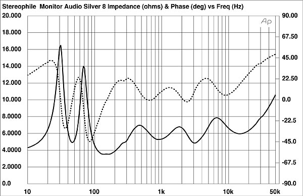
What exactly did you hook up? Speaker impedance varies by frequency, so to say you measured the impedance means you measured the magnitude and angle from 20 Hz to 20kHz.
From Stereophile, here is a typical impedance measurement:
If you were measuring resistance, and that magically changed and would not come back chances are you disturbed a connection somewhere.
Best,
E
From Stereophile, here is a typical impedance measurement:
If you were measuring resistance, and that magically changed and would not come back chances are you disturbed a connection somewhere.
Best,
E
Howdy Ed, thanks kindly for your reply.
The circuit is pictured. The integrity of connections isn't the issue afaik. Point is, I can measure driver D at freq. F and level L - then after moving the cone & coil (rapping on it, etc) it will not settle back to the same impedance. And the shift isn't trivial, either..
What exactly did you hook up?
The circuit is pictured. The integrity of connections isn't the issue afaik. Point is, I can measure driver D at freq. F and level L - then after moving the cone & coil (rapping on it, etc) it will not settle back to the same impedance. And the shift isn't trivial, either..
Last edited:
I read an early version without your pic. ")
That would be unusual in a working speaker. This points to mechanical friction or electrical resistance.
Double check your Vmeter battery? Just thinking of things.
By connections, I include the point to poitn wiring of the crossovers and internal wiring of the speakers.
That would be unusual in a working speaker.
This points to mechanical friction or electrical resistance. Double check your Vmeter battery? Just thinking of things.
By connections, I include the point to poitn wiring of the crossovers and internal wiring of the speakers.
Last edited:
You might try connecting a 1.5volt battery across the speaker in an intermittent way in order to produce 'clicks' from the driver and then in the reverse connection. This might free up the suspension of the driver for it to return to normal.
All one can do is experiment a little and observe the result.
There may have been a DC component flowing in the test circuit at the time of testing and then having tapped the cone it has reset itself to what is normal, thus the impedance might now be a different value. Loudspeaker drivers have a limited Xmax (limited linear movement) particularly small drivers and such may only be 2 millimetres thereabout.
Take care not to be too heavy handed when doing such things.
C.M
So am I correct, in that the impedance of a driver will vary, depending on the position of the voice coil in the gap? That is, if the resting point of the cone (and hence, the voice coil) are a little further 'in' or 'out' of the gap, after being disturbed, will change the 'static' Z of the driver?
I am seeing changes of well over 10% simply by doing a little knock-around with either the bare driver or the speaker. And yes - I give the instruments time to settle. The meter in use is a cal'd Fluke 8050A.
FYI, the 'speakers' here are little KLH 2-way bookshelf models.. model is KLH 9900 Satellite. 8R. They are cast-offs from some HT system or whatnot. Just keep them around for utility purposes.
Last edited:
Well check both of them. In theory, any resistor in place will work, assuming your measurement tools have enough resolution, and/or your input voltage is high enough maybe try smaller?
Try something around 10 Ohms so you have enough signal to move the driver. With a 4 Ohm speaker, the voltage at the meter could be very small. I've not tried making my own rig, but worth trying. Best,
E
Have a read of sb-accoustics document on measuring T/S params http://www.sbacoustics.com/index.php/download_file/-/view/191/
Tony.
Tony.
If you are measuring the impedance of a woofer at higher frequencies, the impedance will vary a fair amount depending on the voice coils rest position. Generally the father towards the back of the motor, the greater the inductance and the higher the impedance.
In addition at low frequencies, the impedance will change for a time period after disturbing the driver due to mechanisms related to creep. This behavior is quite complex.
In addition at low frequencies, the impedance will change for a time period after disturbing the driver due to mechanisms related to creep. This behavior is quite complex.
Thanks to everyone who has commented on this issue.. your inputs are very much appreciated.
Good idea, Ron. Taking the previous comments into account, let me collect another set, and see what I find.. I'll take two series of readings on the same LS - first, with only minimal disturbance (rested overnight) and a second, after knocking it gently on the table a dozen times, at various orientations. Not very repeatable, but from what I've seen it should be enough perturbation to produce the effect in question.
Give me an hour or two to get this done, and I will report back. BTW - who here knows how to create charts in LibreOffice Calc? That's something else I need to know.
Show the data, otherwise people are interpreting the question rather than the data.
Good idea, Ron. Taking the previous comments into account, let me collect another set, and see what I find.. I'll take two series of readings on the same LS - first, with only minimal disturbance (rested overnight) and a second, after knocking it gently on the table a dozen times, at various orientations. Not very repeatable, but from what I've seen it should be enough perturbation to produce the effect in question.
Give me an hour or two to get this done, and I will report back. BTW - who here knows how to create charts in LibreOffice Calc? That's something else I need to know.
First round of new data, from the 4" bare driver. Readings are taken with the driver resting on the magnet structure, with the VC directed upwards.
Bare 3" driver - after 24 hrs. rest.
(Hz - impedance)
20 - 6.79
25 - 6.92
31.5 - 7.16
40 - 7.57
50 - 8.36
63 - 10.34
71 - 12.66
80 - 15.17
100 - 13.66
113 - 10.87
126 - 9.37
159 - 7.73
180 - 7.36
193 - 7.22
It will be interesting to see how this compares to the next set. This is a limited set, spanning 20Hz - 200Hz, so one decade. But it seems as if there's a significant peak in this range (take a look at 80 Hz area) so it's useful.
A little more info on the driver. It's not actually 4" (102mm) more like 3.5" (89mm)
3.0" / 76mm shielded magnet structure, 3.5" / 89.0mm cone, black rubber surround, composite cone (yellow in color, has woven pattern), mass 22oz / 620gm. Marked: "55-1500 "8 Ω" "MADE IN TAIWAN" on the back side of the magnetic shield. Seems to be of middle-range quality.. better than total crapola, but not anything hi-flying. Serviceable item?
ETA: Found it in the MCM catalog. They call it a 4" driver, and it's near the bottom of p.3 in this PDF.
Last edited:

And here's the second set.. notice that there is missing data point from each set (got bad data and just ignored it, trends are clear, doesn't affect the results).
Bare 4" driver - after moderate disturbance.. pushed & pulled the cone, rapped the structure on the tabletop many times at multiple angles, etc.
20 - 6.90
25 - 7.05
31.5 - 7.29
40 - 7.80
50 - 8.73
63 - 11.1
71 - 13.47
80 - 15.7
100 - 13.0
113 - 10.6
126 - 9.21
143 - 8.23
159 - 7.74
180 - 7.34
200 - 7.14
And imagine that, now they are tracking - quite well, really! So next, I need to run sets using the original 2-way KLH speaks, and see what those yield.
What's this about - hard to believe it's break-in, being that the driver has almost zero time on it, as far as playing real music.
Last edited:
Puzzling. Speaker ought to return to static status unconditionally, AFAIK. Can we assume the speaker plays OK?
Long ago, there was parameter of interest called something like "blocked voice coil impedance" which reflected impedance in the absence of back-EMF.
Could it be some faulty capacitors inside the crossover? Esp if crossover is low and electrolytic used.
Deteriorating insulation on VC in a waterfront atmosphere?
When I was at Bell Labs, the standard in our department was the KLH 6. Possibly "Bicycle Built for Two" will sound better if you play it on one. The KLH model you mention might be "KLH" in name only, as a brand but not related to the old company.
B.
Last edited:
Looks like suspension creep, as someone else said already.
Same thing would happen if you blasted the driver with 20 Hz to near xmax between measurements. The spider in a speaker is not terribly linear. It gets stiffer with excursion, but perhaps paradoxically the resonant frequency goes down as you increase amplitude. It remains lower for a while after the stimulus, then typically "recovers" after a time. For the high frequency differences, the operating point may have shifted a bit and your signal isn't strong enough to move it back.
Graphing in libre office or excel is quite easy, put your data in columns, then select it and click a button and follow a couple prompts. For graphing data, use a scatter plot, then you can later doubleclick the axis and choose a log scale.
@Ron E
Interesting. This 'creep' factor is new to me, which isn't so surprising - I don't know squat about LS physics. But I have noticed that it seems to take forever for some of the readings to stabilize.. and in fact, I've had to make a number of arbitrary calls on when to log the reading, as settling time wasn't part of the original measurement spec.
I need to learn more about susp. creep, it seems that it might be a factor in this case.
@bentoronto
Heh.. 'No', as it's never been put to use. But 'Yes', as it appears to be NIB - never used.
How is this done? Is the goal to immobilize the cone / voice coil such that it remains in-place, rather than oscillating as intended? In short, to make the vc & magnet behave more like a fixed inductor?
In the case of this 4" (3.5") bare driver, there are no crossover components. It's bare, on the bench, cone facing upwards.
Not recently, I'm far inland (St. Paul, MN, USA)
Yes, the model I'll test next is the 'KLH' bookshelf LS. The model number is given, above. It's more like a satellite speaker for a HT system, but to me it's a bookshelf. It was this pair that had the greatest deviation in the readings. The woofer is maybe 3" and the tweeter like 3/4"?
@ All
Thanks so much for your input on this. I'll run a similar test on the KLH's now, and see what I see. As with the previous sets, I will try to find a low-freq impedance peak, and center the measurements around that.
Looks like suspension creep, as someone else said already.
Interesting. This 'creep' factor is new to me, which isn't so surprising - I don't know squat about LS physics. But I have noticed that it seems to take forever for some of the readings to stabilize.. and in fact, I've had to make a number of arbitrary calls on when to log the reading, as settling time wasn't part of the original measurement spec.
I need to learn more about susp. creep, it seems that it might be a factor in this case.
@bentoronto
Puzzling. Speaker ought to return to static status unconditionally, AFAIK. Can we assume the speaker plays OK?
Heh.. 'No', as it's never been put to use. But 'Yes', as it appears to be NIB - never used.
Long ago, there was parameter of interest called something like "blocked voice coil impedance" which reflected impedance in the absence of back-EMF.
How is this done? Is the goal to immobilize the cone / voice coil such that it remains in-place, rather than oscillating as intended? In short, to make the vc & magnet behave more like a fixed inductor?
Could it be some faulty capacitors inside the crossover? Esp if crossover is low and electrolytic used.
In the case of this 4" (3.5") bare driver, there are no crossover components. It's bare, on the bench, cone facing upwards.
Deteriorating insulation on VC in a waterfront atmosphere?
Not recently, I'm far inland (St. Paul, MN, USA)
The KLH model you mention might be "KLH" in name only, as a brand but not related to the old company.
Yes, the model I'll test next is the 'KLH' bookshelf LS. The model number is given, above. It's more like a satellite speaker for a HT system, but to me it's a bookshelf. It was this pair that had the greatest deviation in the readings. The woofer is maybe 3" and the tweeter like 3/4"?
@ All
Thanks so much for your input on this. I'll run a similar test on the KLH's now, and see what I see. As with the previous sets, I will try to find a low-freq impedance peak, and center the measurements around that.
Last edited:
- Status
- This old topic is closed. If you want to reopen this topic, contact a moderator using the "Report Post" button.
- Home
- Loudspeakers
- Multi-Way
- Speaker measurement difficulty - What's up?