Good work looks like you are closing in ") For your correction have you used minimum phase EQ and then removed the excess phase, I think from memory that was the way swiss bear went?
For your correction have you used minimum phase EQ and then removed the excess phase, I think from memory that was the way swiss bear went?
From doing a similar thing recently I would say to look how closely the IR peaks are aligned before you average them. For me REW did not do a great job of doing it with the time align function. Your's might be different but it does have an effect on the high frequencies if the impulses aren't within a certain tolerance when they are averaged. Make sure the averages are run on raw data too just to be sure, leave any windows or smoothing for after.
The impulse averaging weights the dips more than the peaks, have a look in the all spl window with all of the individual measurements open to see if there are any areas where the average is not representative of the majority of positions. EQ'ing those up could result in peaks which might be more objectionable than a dip.
Have a look at the frequency response through a Frequency dependant window too, if there are any areas where there are a number of dips close together they will show up quite clearly, those are the trouble spots.
The spectrogram is a good way of looking at the time data too.
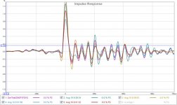
Impulses are tricky to interpret sometimes, there is some unusual pre-ringing in yours. That could be the result of phase correction or something funky in your chain. Take a loopback measurement of your soundcard to see and set the processing to flat to see if there is a change there. Some DAC's have some quite strange impulse responses due to their filtering.
For your correction have you used minimum phase EQ and then removed the excess phase, I think from memory that was the way swiss bear went?From doing a similar thing recently I would say to look how closely the IR peaks are aligned before you average them. For me REW did not do a great job of doing it with the time align function. Your's might be different but it does have an effect on the high frequencies if the impulses aren't within a certain tolerance when they are averaged. Make sure the averages are run on raw data too just to be sure, leave any windows or smoothing for after.
The impulse averaging weights the dips more than the peaks, have a look in the all spl window with all of the individual measurements open to see if there are any areas where the average is not representative of the majority of positions. EQ'ing those up could result in peaks which might be more objectionable than a dip.
Have a look at the frequency response through a Frequency dependant window too, if there are any areas where there are a number of dips close together they will show up quite clearly, those are the trouble spots.
The spectrogram is a good way of looking at the time data too.
Impulses are tricky to interpret sometimes, there is some unusual pre-ringing in yours. That could be the result of phase correction or something funky in your chain. Take a loopback measurement of your soundcard to see and set the processing to flat to see if there is a change there. Some DAC's have some quite strange impulse responses due to their filtering.
Good work looks like you are closing in
That's correct, it was min phase and remove excess. My amplitude corrections were manual in RePhase only, I prefer to match the filter [fc, G, Q] to the response defect. I have only corrected (so far) using the standard EQ PK forms
From doing a similar thing recently I would say to look how closely the IR peaks are aligned before you average them. For me REW did not do a great job of doing it with the time align function. Your's might be different but it does have an effect on the high frequencies if the impulses aren't within a certain tolerance when they are averaged. Make sure the averages are run on raw data too just to be sure, leave any windows or smoothing for after.
Good suggestion. I have not paid much attention to alignment. I just let REW generate min phase and remove offsets. The FR data was raw before averaging.
The impulse averaging weights the dips more than the peaks, have a look in the all spl window with all of the individual measurements open to see if there are any areas where the average is not representative of the majority of positions. EQ'ing those up could result in peaks which might be more objectionable than a dip.
Looks like you want to remove the "outliers". None of them looked weirder than the others. Maybe I'll try some subset combinations.
Have a look at the frequency response through a Frequency dependant window too, if there are any areas where there are a number of dips close together they will show up quite clearly, those are the trouble spots.
The spectrogram is a good way of looking at the time data too.
It is possible that my manual corrections, actually corrected things that were not there
There was no FDW performed before averaging. I'll see if any weirdness remained via FWD on the avg.Impulses are tricky to interpret sometimes, there is some unusual pre-ringing in yours. That could be the result of phase correction or something funky in your chain. Take a loopback measurement of your soundcard to see and set the processing to flat to see if there is a change there. Some DAC's have some quite strange impulse responses due to their filtering.
Lookback may be a problem. My output chain is [PC]->S/PDIF->RVX659->speaker. My input chain is [Mic]->[PC] . I might be able to take a line out from the amp to line in on the PC for loopback.
Thanks again for the help.
Not quite what I meant, it might be that in the area you measured and with your speakers being omni you didn't get anything that was not representative in the average.Looks like you want to remove the "outliers". None of them looked weirder than the others. Maybe I'll try some subset combinations.
Because the dips are weighted more heavily it is possible when impulse averaging for a dip to appear in the average which is worse than reality if that makes sense. Correcting that might be an overcorrection in reality.
You can check afterwards in the same positions to make sure you didn't overdo anything.It is possible that my manual corrections, actually corrected things that were not there
Only use the FDW to view the average afterwards don't use FDW before averaging that will give weird results I would think.
It is very hard to get a good impulse when the input and output cards are run on different clocks. For measurement it is much better to use the same soundcard as input and output device if possible.Lookback may be a problem. My output chain is [PC]->S/PDIF->RVX659->speaker. My input chain is [Mic]->[PC] . I might be able to take a line out from the amp to line in on the PC for loopback.
Thanks again for the help.
I had the same issue when I used my USB connected DSP board as output and then measured via my Focusrite soundcard. I got a much cleaner impulse when using the Focusrite for playback and recording.
Happy to help where I can
.... These are all measured at my listening position 2.4m from the speakers with no room treatment and no subwoofer.
Don, I just noticed this thread. As per my own experience with measurements, you have a major basic fault now. You show measurements done at farfied in a normal room, obviously with standard 500ms gating. That is totally wrong type of measurement to equalize and rephase a speakers output/phase! You see just summation of hundreds of in-room reflections and modes. This method is ok for low frequency eq or tonal balance adjustment with 1/2 octave smoothing.
To analyze and adjust a loudspeakers output (frequency response at various angles, phase response, step response, distortion, mechanical resonances etc.) you must do nearfield measurements at say 0.6 to 1m distance, with the speaker in the middle of the room and analyze the measurement with IR gating (right window) set to say between 3-9ms. First boundary reflections usually start showing already at 2.5-3ms!
A good link to how to do it right https://www.minidsp.com/applications/acoustic-measurements/loudspeaker-measurements
Last edited:
Don, I just noticed this thread. As per my own experience with measurements, you have a major basic fault now. You show measurements done at farfied in a normal room, obviously with standard 500ms gating. That is totally wrong type of measurement to equalize and rephase a speakers output/phase! You see just summation of hundreds of in-room reflections and modes. This method is ok for low frequency eq or tonal balance adjustment with 1/2 octave smoothing.
To analyze and adjust a loudspeakers output (frequency response at various angles, phase response, step response, distortion, mechanical resonances etc.) you must do nearfield measurements at say 0.6 to 1m distance, with the speaker in the middle of the room and analyze the measurement with IR gating (right window) set to say between 3-9ms. First boundary reflections usually start showing already at 2.5-3ms!
A good link to how to do it right https://www.minidsp.com/applications/acoustic-measurements/loudspeaker-measurements
There may be a misunderstanding in what is being attempted here.
My earlier measurements have been near field (1m) as you've suggested, and they were used to correct speaker issues. I have a preferred location for these near field measurements that has minimal room reflections.
This latest set of measurements treats the speaker and room as a system and takes multiple measurements around the listening area. In my case its a smallish sweet spot around my listening couch. It's an attempt to get corrected sound to the ears. It excludes LF (<100Hz) as these are room modes. Overall this system correction sounds better than the speaker specific near field corrections.
Ok sorry I didn't read through the whole story.
But please do many measurements with varying speaker an mic location to learn what reflections cause which dips and peaks. Also for farfield eq use smoothing 1/2 or 1/3 and don't do any eg operations that are narrower either!
Moving Microphone Measurement technique (MMM) with RTA or averaging of several measurements is also helpful
http://www.ohl.to/audio/downloads/MMM-moving-mic-measurement.pdf
Moving Mic Measurement
But please do many measurements with varying speaker an mic location to learn what reflections cause which dips and peaks. Also for farfield eq use smoothing 1/2 or 1/3 and don't do any eg operations that are narrower either!
If you read the whole thread you would see that Don has taken a lot of close up measurements and measurements around a full 360 to verify that his speaker was acting as an omni.
I would agree that getting as close to anechoic measurements as you can is a good idea for setting up crossovers, looking for resonances etc. Don't be too quick to think that you it is not possible to use more detailed EQ when measured from a distance. It just needs some thought and understanding of what you are doing.
Don is using a spatial averaging technique which helps to avoid overcorrection and includes the most persistent room issues. While many people have done room EQ very badly in the past it doesn't mean that some of the software and techniques cannot be used in a better way and achieve good results.
Moving microphone is a form of spatial averaging that discards phase. That can be useful but so can impulse averaging. If you haven't seen it before have a read of the paper on the beamforming measurement method. They use a straight line but the principle is the same.
By using enough averages you can really suppress the room contribution and are only left with significant modal and non position dependant room issues in the measurement. Those are actually useful if you want to try and improve them through EQ and processing rather than acoustic means.
It's always better to deal with a problem at the source but not everyone has that luxury.
Impulse response improvements via DRC
In an earlier test, RePhase was used to correct the avg room FR room response but resulted in a poor impulse response OmniDirectional - work in progress .
With some generous help from @Fluid, who used another tool (DRC) to create a filter than cleaned up the impulse response significantly.
Both the RePhase corrections and the DRC corrections significantly cleaned up the measured responses and improved the sound quality. This is the best Omni solution to date and its time to repackage it into something more finished looking.
Attachments
Compared to what ?
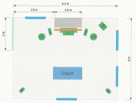
This is a comparison to other speaker solutions. The OmniV4 has compensation as previously described. The listening room I use is setup as per the attached pic. The signal path is [PC] -> S/PDIF -> RXV659 -> Speakers. Stereo upmixing is in the RXV659 but Yamaha does not disclose the algorithms. The comparison set are Paradigm [monitor 7v5 for LR, mini monitors for SR+SL, PDR10 sub, CC370 center]
1) Paradigm Stereo 2.0
- normal stereo, phantom center slightly behind mid speaker line
- sound stage generally as wide as the speakers
- the room is wide enough that there's little lateral reflections from these
- these are 2.5 way tower speakers, and bass is weak
2) Paradigm Stereo 2.1
- same as above only the bass is improved (XO=80Hz)
- its a narrow slice (30-80Hz) but makes a huge improvement to the sound
3) Paradigm Stereo upmix 3.1
- center speaker (2 way MTM) is on
- stereo center is more solid (less position sensitive) + forward of LR pair
- relative volume w.r.t LR pair can move position forward
- sound stage width the same as 2.0
4) Paradigm Stereo upmix 4.0
- front LR and side LR (2way) are on
- still has the phantom center like 2.0
- the sides can be used to delay sound to mimic a larger room
- just like an acoustic center for the front, there is one for the side now
- sound stage is much wider than 2.0 from lateral sound
- phantom center appeared to move forward in line with speakers
5) Paradigm Stereo upmix 5.1
- very wide soundstage and solid stereo center
- like the 4.0, lateral sound widens the stage
6) OmniV4 Stereo 2.0
- phantom center is aligned to LR pair
- soundstage is wider than Paradigm 2.0 not as wide as Paradigm 5.1
- bass from 8" driver insufficient for this room
7) OmniV4 Stereo 2.1
- same as OmniV4 stereo 2.0 only the bass is improved (XO=80Hz)
Attachments
Last edited:
Omni V5 - construction - cones
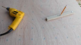
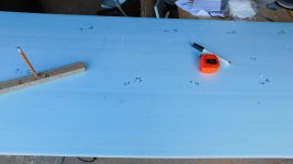
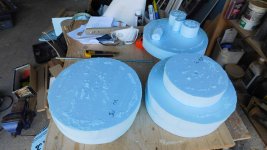
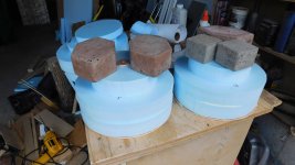
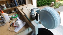
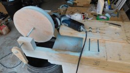
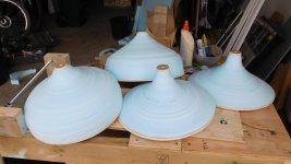
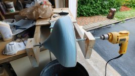
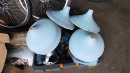
These are some construction pics for V5. Probably the hardest construction detail is making the cone shapes. It can be done in 3D printing or fiberglass molds but there is another easier means. Generating the profile can be done in an excel spreadsheet and cut into a ply sheet as a "slot" . Its fairly easy to make a curve tracing fixture, that will allow a grinder to follow the profile slot to initially bulk machine polystyrene foam. The fixture can then be reused with a variable speed hand drill to spin the workpiece like a wood lathe to sand smooth the surface. These are common hand tools on hand, and the fixture is scrap wood with $20 of bushings, bolts and collars. The foam+sureply backing is about $6 per cone. The tips and final painting will be added later.
These are some construction pics for V5. Probably the hardest construction detail is making the cone shapes. It can be done in 3D printing or fiberglass molds but there is another easier means. Generating the profile can be done in an excel spreadsheet and cut into a ply sheet as a "slot" . Its fairly easy to make a curve tracing fixture, that will allow a grinder to follow the profile slot to initially bulk machine polystyrene foam. The fixture can then be reused with a variable speed hand drill to spin the workpiece like a wood lathe to sand smooth the surface. These are common hand tools on hand, and the fixture is scrap wood with $20 of bushings, bolts and collars. The foam+sureply backing is about $6 per cone. The tips and final painting will be added later.
Attachments
-
 Omni cone mill reduced.jpg186.6 KB · Views: 401
 -
 DSCN2024 reduced.jpg734.2 KB · Views: 399
 -
 DSCN2026 reduced.jpg338.2 KB · Views: 365
 -
 DSCN2027 reduced.jpg488.8 KB · Views: 166
 -
 DSCN2029 reduced.jpg429.7 KB · Views: 184
 -
 DSCN2032 reduced.jpg624.5 KB · Views: 209
 -
 DSCN2033 reduced.jpg623.8 KB · Views: 209
 -
 DSCN2035 reduced.jpg389.9 KB · Views: 228
 -
 DSCN2036 reduced.jpg702.1 KB · Views: 228
 -
 DSCN2038 reduced.jpg586.5 KB · Views: 235
Last edited:
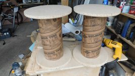
Omni V5 - construction - stands
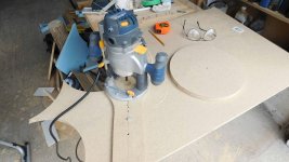
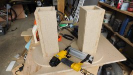
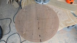
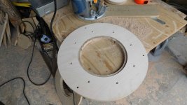
The theme is polar symmetry. Stands are required for these speakers to decouple from the floor. The discs are cut using a router and scrap wood router circle guide. The post structure is 2mm particle board glued and stapled. The post long edges are mitered to just fit inside a 6" concrete former tube. The end disks have a 3mm deep channel to hold the tube in place, and in slight compression. The discs have 1/2" rounded edges just for aesthetics. It sounds fairly dead, but I may add sand if I suspect a problem later. I also like concrete fill but that may be too heavy. Finishing (black paint or birch veneer) will come later as will addition of carpet spikes and cork/rubber antislip pads.
The theme is polar symmetry. Stands are required for these speakers to decouple from the floor. The discs are cut using a router and scrap wood router circle guide. The post structure is 2mm particle board glued and stapled. The post long edges are mitered to just fit inside a 6" concrete former tube. The end disks have a 3mm deep channel to hold the tube in place, and in slight compression. The discs have 1/2" rounded edges just for aesthetics. It sounds fairly dead, but I may add sand if I suspect a problem later. I also like concrete fill but that may be too heavy. Finishing (black paint or birch veneer) will come later as will addition of carpet spikes and cork/rubber antislip pads.
Attachments
Last edited:
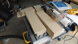
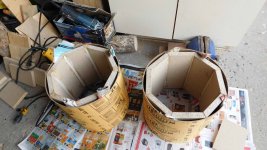
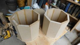
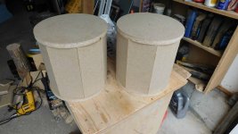
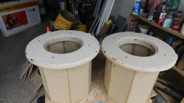
Omni V5 - construction - Woofer Chamber
This is a 16L chamber for a BR design. I have a few experiments left to do on the older V4 box w.r.t the port design for V5. The more sides, the more cylindrical it would be, but I stopped at 8 sides. With the top and bottom on, it is very dead sounding. The short panel dimensions make it stiffer and any parallel surfaces are small. The "skin" will make it a perfect cylinder w.r.t external boundary effects. The small cylinder-octagon gaps will be filled with polyester fill forming a damping layer around a stiff core. The cylinder will be finished in birch veneer or painted black (still deciding).
This is as far as I got because I burned the brushes out of my router. New ones are in transit, and I should be back up and running in a couple of days
Attachments
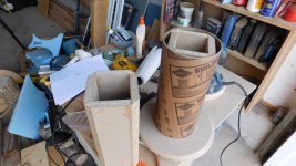
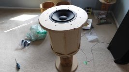
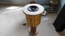
Omni V5 - construction - port position
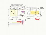
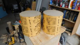
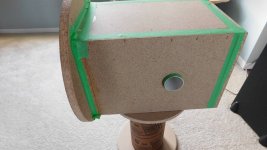
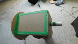
This question always comes up, "where is the best location for the port". So I took a V4 chamber, removed the XO, removed all poly fill, and tested 20-2000Hz using REW. I tried the tuning pipe inside, pipe protruding outside, pipe on the side, and pipe on the bottom. Pipe on the bottom starts to look like MLTL and for these configurations HornResp indicates the same performance. The green tape is residue from a leak test, there are none (detectable).
I've posted pics of the port positions and tuning pipe, plus the graphs. The pipe is the same diameter (5x13cm) in all cases. It seems the port position does not matter for these tested locations. The V5 would look cleaner with a radial port on the bottom to avoid pipe holes on the chamber side. Looks like that will work.
Attachments
I am planning to use a sub XO @ 80Hz so technically there is no reason. However with a bottom port I can try both ported and sealed using a 16L chamber. It's easy to cover /cap the internal bottom hole and see what sound I prefer. I did test the V4 closed and it has lower distortion than ported and it rolls off earlier as expected.
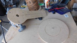
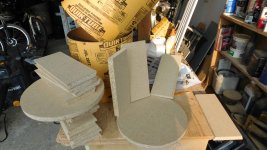
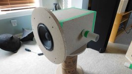
OmniV5 - Construction - Woofer Baffle + Test
Next is the woofer baffle plate. Its smaller than the V4 (36cm vs 40cm) and is designed as two parts to increase edge radius. Only the upper portion is in the pics. There are multiple angles and holes to be drilled so another template is created from sureply to make it easier to transfer the exact locations to each workpiece. The assembled structure is very dead sounding when its tapped.
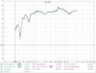
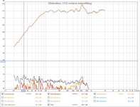
The woofer chamber was tested with 1/2 loose poly filled chamber, no XO, as a sealed 16L chamber. The roll off starts at 100Hz as expected and drops in a predictable manner (2nd order, 12db / octave). It has none of the boominess that the BR or ABC designs had. I think I'll keep it like this to see how it behaves as a system. I can easily had a bottom port before finishing if I change my mind.
The +3db peak at 630Hz is due to the distance behind the woofer (27cm) which at 1/2 lambda away puts it at (344 / (0.27 *2))=637Hz. Measurements are nearfield at 10cm.
Next is the woofer baffle plate. Its smaller than the V4 (36cm vs 40cm) and is designed as two parts to increase edge radius. Only the upper portion is in the pics. There are multiple angles and holes to be drilled so another template is created from sureply to make it easier to transfer the exact locations to each workpiece. The assembled structure is very dead sounding when its tapped.
The woofer chamber was tested with 1/2 loose poly filled chamber, no XO, as a sealed 16L chamber. The roll off starts at 100Hz as expected and drops in a predictable manner (2nd order, 12db / octave). It has none of the boominess that the BR or ABC designs had. I think I'll keep it like this to see how it behaves as a system. I can easily had a bottom port before finishing if I change my mind.
The +3db peak at 630Hz is due to the distance behind the woofer (27cm) which at 1/2 lambda away puts it at (344 / (0.27 *2))=637Hz. Measurements are nearfield at 10cm.
Attachments
That response looks very nice to work with your sub. If you can get some fibreglass to use as stuffing try it out, poly is hopeless for damping resonances etc. Check the impedance response with REW and a resistor jig you will be able to see where all the cabinet based bumps are and which stuffing lowers them.
Looks like V5 won't be too far from finished soon
Looks like V5 won't be too far from finished soon
I agree, the response is well behaved, and would work nicely with my sub. I don't need these sections while I'm working on the upper half of the speaker. I'll play around with the combined responses to see how smooth the sub transition is.
Given that the internal reflection is specific at 630Hz, it might be better to EQ in passives or s/w. I'm not sure I can get filling to be that specific. I've never used the REW impedance measurement, I'll look into it.
Probably need another week for the upper sections and I'll have a functioning V5 ,without the paint or veneer. I prefer to build and verify before spending any effort on the cosmetics.
As the peak corresponds with the size of pipe it's sounds like a pipe resonance. You can EQ it but if you can stop it at the source that has to be better.
Try some fibreglass it is very good at damping the rear wave and cabinet resonances and you will need much less of it to have a positive effect. Poly stuffing is good for increasing the apparent volume of the enclosure but it does almost nothing for resonances unless you really pack it in. Felt works very well too.
Impedance Measurement Make the jig shown here with a known resistance and you can see what the cabinet is adding. If the bumps correspond with a change in frequency response then you could make them better through damping.
Wesayso convinced me to do some tests of the different materials. The impedance plot shows their effects and takes the guesswork out of getting it right.
If you do decide to port it checking the impedance is the best way to get the tuning right. All it takes is a couple of connectors, wire and resistor.
- Home
- Loudspeakers
- Multi-Way
- OmniDirectional - work in progress