Thanks for the suggestions.BTW, Don, here's a Visaton SC5 tweeter that I thought could make a good supertweeter above 5kHz. Because most of the 1" and bigger tweeters have dispersion problems at the top end.
SC 5 - 8 Ohm
I really have no idea how it sounds, but the regular mylar sound, you'd guess. And I don't think the ear is very discriminating above 10kHz anyway.
A 0.5" dome ought to have very good and flat power response up to the limit of audibility. Cheap enough to use several, if you wanted too. Audax make one like this too.
My experience so far, with firing a dome into a reflector, has been that it resulted in too much loss and possible interference patterns. I also need to go down to 1.8Khz. My sandbox is intentionally restricted to a 2 way to make it easy for me to try ideas. Once I "get it working" the omni shape will be refined and it will emerge as a 3/4 way in a more eye pleasing package.
I'll be using a Dayton Audio H10RW 10″ Round Waveguide (good down to 1.6Khz) coupled to a Fane CD-130 compression driver. If it works as advertised, I'll get 106db/W and a properly formed wavefront into the reflector. Once I remove my approx 10db path loss I'm left with 96db to the air. Enough margin for tweaking.
I was thinking of an compact explanation for this.Thanks. Same here, only found it after EQing LF and then measuring. I shall follow this thread with interest....
At Fc, spice shows -6db which is a voltage measurement. So 20*log(Vo/Vi)=-6db or 10^(-0.6)=0.5, meaning the voltage applied to a driver is down to 0.5 w.r.t input. If you prefer vectors the voltage is [0.486+0.12j] which is the same as -6db.
If you add those vectors, or the db voltages you will be back to 0.5+0.5=1.0 and spice shows a flat voltage response or 20*log(1/1)=0db. This is where I missed it the first time.
Power is essentially proportional to v^2, so if we had 0.5 voltage we get 0.25 power at each driver. Adding 0.25+0.25=0.5 power total, or 10*log(P1/P2)=-3db . Presto.
A side note : the polynomial that created LR4 (double cascaded 2nd order Butterworth) ensures uniform (linear) phase response and group delay and maximum flattness (of voltage). Its what makes it special. You can tweak it alittle but at some point you will degrade those qualities. You cannot arbitrarily select different cutoff frequencies as they are matched in a 2way. I need to fix mine and I can share a solution, as I want to minimize the parts count change.
I did. See earlier in the thread. Is a lower reflector needed?
You did a measurement, I mean extensive listening.
no, You don't need any reflectors, rather a reflecting ceiling
Power is essentially proportional to v^2, so if we had 0.5 voltage we get 0.25 power at each driver. Adding 0.25+0.25=0.5 power total, or 10*log(P1/P2)=-3db . Presto.
Ha, yes of course, sometimes it's hard to see the wood for the trees.
A side note : the polynomial that created LR4 (double cascaded 2nd order Butterworth) ensures uniform (linear) phase response and group delay and maximum flattness (of voltage). Its what makes it special. You can tweak it alittle but at some point you will degrade those qualities. You cannot arbitrarily select different cutoff frequencies as they are matched in a 2way. I need to fix mine and I can share a solution, as I want to minimize the parts count change.
I should like to see your solution. For completeness, my xover is at 125Hz, which is too low for Jordan Eikona in open baffle, although it is effectively quite large.
I have tried to divide this quote, hope it's worked
") No not quite as I intended, I am guilty of inserting something into yours above. Can someone tell me how to do this please
No not quite as I intended, I am guilty of inserting something into yours above. Can someone tell me how to do this please
Last edited:
I understand what you mean. I have temporarily tried this when I was testing the XO, speakers on the floor pointed up to the ceiling. The sound does reflect.You did a measurement, I mean extensive listening.
no, You don't need any reflectors, rather a reflecting ceiling
I have a cathedral ceiling but it's been stippled so it acts like a diffuser, and I have floor with carpets which act as an absorber. So the sound does reflect from the ceiling but I wouldn't be able to tell left from right and its does not reinforce the incident wave properly, at least not to my ears. I do plan on using the ceiling in the future when this project becomes a hemispherical radiator, in an attempt to add more "spaciousness".
Don, no idea if it would improve anything, but just a quick thought
You documented problems with firing a tweeter into a cone due to the radiation directivity of such a small acoustic radiator.
Possibly a larger fullrange radiator would give better results by using the natural beaming of high frequencies? The 3.5" TC9FD is exceptionally flat for a full-range and cheap around $11. Should start beaming around 3khz due to it's size.
It would also be interesting to see if there are any differences firing into a cone, a "reverse horn" shape (no idea what to call this), a half hemisphere, and a full sphere.
Another idea is using a compression driver mounted to a 360 degree horn.
Last edited:
Good suggestions. Beaming does help as I see an improvement at the higher freq. However its not the only problem. The drivers suffers from high attenuation as the pressure is spread from 120deg (or less) out to 360deg (reflector).
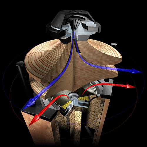
Next up is a waveguide and a compression driver. I should have the parts and results by end of this week. I believe that's what the Duevel (in your image) is doing. I'll be using a Dayton Audio H10RW 10″ Round Waveguide (good down to 1.6Khz) coupled to a Fane CD-130 compression driver.
Next up is a waveguide and a compression driver. I should have the parts and results by end of this week. I believe that's what the Duevel (in your image) is doing. I'll be using a Dayton Audio H10RW 10″ Round Waveguide (good down to 1.6Khz) coupled to a Fane CD-130 compression driver.
Last edited:
Ahh yes, that makes sense that the radiation pattern effects SPL at distance.
If this is the problem and the above full-range driver configuration worked wonderfully, you could increase efficiency by an omni line array; using a tower of half-sphere enclosures firing into back of the next enclosure.
There are many ways to skin a cat, for sure!
Good luck with the experiment! I'll be watching this for sure
Last edited:
I wonder if you could achieve this HF dispersion pattern with two identical waveguides "nested"?
Tweeter mounted to plywood panel, facing up.
First waveguide mounted to this base panel, exit points up also.
Second waveguide suspended above "fixed" assembly, with mounting flange capped.
This would allow tuning if the nested guides can be adjusted to control the gap created.
http://www.daytonaudio.com/index.ph...ides/h10rw-10-round-waveguide-1-threaded.html
Sent from my Nexus 6 using Tapatalk
Thanks. I'll try it and post results, its an easy experiment. Those are the waveguides I have on order already. If that works it would be a convenient solution, the waveguide and reflector being the same shape. My initial concern was I'd have constant gap width from transducer to exit from nesting identical structures and no control of flare at the exit. We'll know within a week.
Waveguides and compression driver - baseline driver test
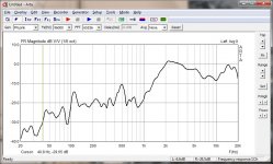
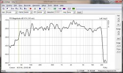
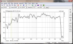
I have Dayton 10" circular wave guides and Fane CD130 drivers to fix the HF issues. This is a quick test to see if they work and if they're consistent before the woodworking starts. I have a few other things to take care of, so actual mounting and reflector test results in 3-4 days.
Now they are loosely sitting on the top on my cabinet as I test and listen to them. They have a different sound compared to dome tweeters so my ears are still evaluating them. The circular waveguides have none of the "honk" or "harshness" of the rectangular horns I've heard, so I'm happy with that.
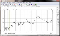
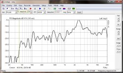
They are extremely efficient, and are 15-20db above my 90db woofer. So the drivers work as advertised 106db/w with these waveguides. Off axis is similar to dome tweeters, they are still good at 30deg but they fall off at 60deg and become more directional at higher freq. The response is clean down to 1.8KHz (probably lower) but hve a dip at @10KHz, and something I'll check into later. Both my waveguides and drivers are virtually identical in performance. Graphs provided.
I have Dayton 10" circular wave guides and Fane CD130 drivers to fix the HF issues. This is a quick test to see if they work and if they're consistent before the woodworking starts. I have a few other things to take care of, so actual mounting and reflector test results in 3-4 days.
Now they are loosely sitting on the top on my cabinet as I test and listen to them. They have a different sound compared to dome tweeters so my ears are still evaluating them. The circular waveguides have none of the "honk" or "harshness" of the rectangular horns I've heard, so I'm happy with that.
They are extremely efficient, and are 15-20db above my 90db woofer. So the drivers work as advertised 106db/w with these waveguides. Off axis is similar to dome tweeters, they are still good at 30deg but they fall off at 60deg and become more directional at higher freq. The response is clean down to 1.8KHz (probably lower) but hve a dip at @10KHz, and something I'll check into later. Both my waveguides and drivers are virtually identical in performance. Graphs provided.
Attachments
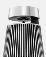
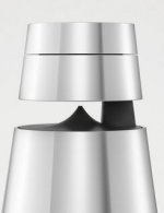
I was looking at some Bang and Olufsen Beosound omnis today. All very wireless, of course. It's the way it's going.
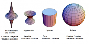
Interesting tweeter construction. Looks like the dome tweeter fires onto a tractrix or pseudosphere shape. Which for those who don't know is a sphere with negative gaussian curvature. I've never been one for reinventing the wheel. It must work.
Interesting tweeter construction. Looks like the dome tweeter fires onto a tractrix or pseudosphere shape. Which for those who don't know is a sphere with negative gaussian curvature. I've never been one for reinventing the wheel. It must work.
Attachments
Coaxial waveguides as a HF reflector
This suggestion was "Originally Posted by anji12305 : I wonder if you could achieve this HF dispersion pattern with two identical waveguides "nested"?
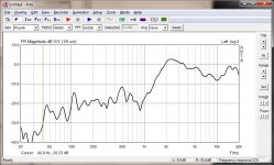
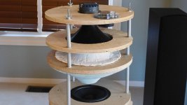
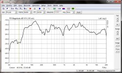
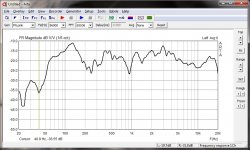
Well, it does work, thanks anji12305. I tried this with different edge to edge waveguide spacings [5cm, 10cm, 14cm, 18cm]. My preferred spacing is between 5-10cm as the curve most ressembles the original baseline waveguide curves. Going too close (<5cm) with a 2cm polystyrene cone cap will actually suppress output from the waveguide. So spacing effects the response curve's frequency dependent attenuation and smoothness. I'll try different shape reflectors to see if I can go better (smoother) than coaxial waveguides.
The compression driver and waveguide still have the expected -8db path loss from a reflector and levels are still about +5db higher than the woofer levels. This would be easy to fix with L-pad attenuation and a bit of equalization at 2.2Khz. The graphs include room acoustics and are measured at 1m out at mid top-middle disc height.
This suggestion was "Originally Posted by anji12305 : I wonder if you could achieve this HF dispersion pattern with two identical waveguides "nested"?
Well, it does work, thanks anji12305. I tried this with different edge to edge waveguide spacings [5cm, 10cm, 14cm, 18cm]. My preferred spacing is between 5-10cm as the curve most ressembles the original baseline waveguide curves. Going too close (<5cm) with a 2cm polystyrene cone cap will actually suppress output from the waveguide. So spacing effects the response curve's frequency dependent attenuation and smoothness. I'll try different shape reflectors to see if I can go better (smoother) than coaxial waveguides.
The compression driver and waveguide still have the expected -8db path loss from a reflector and levels are still about +5db higher than the woofer levels. This would be easy to fix with L-pad attenuation and a bit of equalization at 2.2Khz. The graphs include room acoustics and are measured at 1m out at mid top-middle disc height.
Attachments
-
 DSCN1837 reduced.jpg390.3 KB · Views: 342
 -
 coax waveguide 18cm space amp-25db midgap@1m.jpg130.9 KB · Views: 108
 -
 coax waveguide 14cm space amp-25db midgap@1m.jpg131 KB · Views: 93
 -
 coax waveguide 10cm space amp-25db midgap@1m.jpg131.2 KB · Views: 99
 -
 coax waveguide 5cm space amp-25db midgap@1m.jpg130.5 KB · Views: 307
It sounds pretty good. Huge improvement over a dome tweeter and conical reflector.
Unfortunately I only have 2 waveguides and they're both on the left side now. So the right has a direct firing silk dome that does not match well with a waveguide.
At this point, for listening I use an equalizer to flatten out the 2.2Khz bump and I drop the entire HF section by 6db to balance it out. Listening to Van Morrison, Into the Mystic now
Last edited:
HF Waveguide extended and attenuated
It occurred to me that moving the waveguides closer together just creates another waveguide with a different flare factor. Its no longer a reflector. I've also unsuccessfully tried a HF reflector cone but it experiences the same high freq attn problem as the dome experiments.
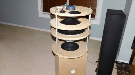
I didn't have enough waveguides, so I made more. A plastic bag, paper towels and some plaster to copy the existing waveguide. The plastic bag left some wrinkles, I'll sand out later, but it works fine.
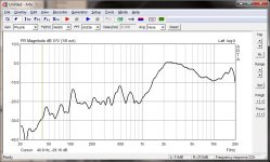
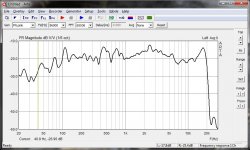
The CD power is reduced with a 5.5R series resistor. It also seems to take down the peak at 2.2Khz. The entire speaker stackup height can now be reduced. The polar response is even enough for evaluation. The measurements include room acoustics.
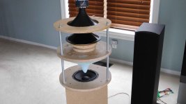
The additional new layer (disc#4) holds a Dayton DC28 that was on hand. Its in in preparation for making this a hemispheric radiator where the tweeter will reflect off the cathedral ceiling. Its pointed straight up.
It occurred to me that moving the waveguides closer together just creates another waveguide with a different flare factor. Its no longer a reflector. I've also unsuccessfully tried a HF reflector cone but it experiences the same high freq attn problem as the dome experiments.
I didn't have enough waveguides, so I made more. A plastic bag, paper towels and some plaster to copy the existing waveguide. The plastic bag left some wrinkles, I'll sand out later, but it works fine.
The CD power is reduced with a 5.5R series resistor. It also seems to take down the peak at 2.2Khz. The entire speaker stackup height can now be reduced. The polar response is even enough for evaluation. The measurements include room acoustics.
The additional new layer (disc#4) holds a Dayton DC28 that was on hand. Its in in preparation for making this a hemispheric radiator where the tweeter will reflect off the cathedral ceiling. Its pointed straight up.
Attachments
Hemispherical
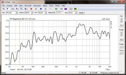
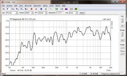
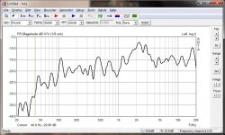
I added attn resistors to balance the waveguide, added the Dayton DC28F back to reflect off the ceiling, and added an L-pad to control the volume directed at the ceiling.
I've include my std measuring position with no/all volume directed at the ceiling. It only makes a 2-3 db difference but you can tell when its on. I've also included a listening position at 2m with both speakers driven. Again the dome tweeter aimed at the ceiling only adds a few db. I prefer it on, as it the sound seems more spacious.
Attachments
-
 DSCN1843 reduced.jpg447.6 KB · Views: 172
 -
 omni L at 1m amp-25db no ceiling refl.jpg124.5 KB · Views: 158
 -
 omni L at 1m amp-25db full ceiling refl.jpg124.8 KB · Views: 88
 -
 omni L&R at listening 2m amp-25db no ceiling refl.jpg130.6 KB · Views: 68
 -
 omni L&R at listening 2m amp-25db full ceiling refl.jpg131.3 KB · Views: 74
- Home
- Loudspeakers
- Multi-Way
- OmniDirectional - work in progress