Lynn, for those of us with less time to wade through the noise of thousands of forum posts, could you share your opinion on the latest generations of very affordable DSP based crossover approaches? I almost said "solutions", but that might seem leading.
+1
The Ariel crossover is 4th-order acoustic at 3.8 kHz, so adjust your active crossover accordingly. The tweeter will never need more than 20 watts, more likely 10 watts in the real world, so you might consider a Class A option for the HF amplifier.
Firstly, thanks for a cool design. It's already providing plenty of enjoyment, and that's just cutting bits of wood up.
Regarding the crossover, I'm thinking a pair of 3rd order Bessels implemented with a discrete opamp I've been playing with. I'll add some baffle step correction to the bass too.
I don't really do class-a amps, except for work. The amp I'll use for this is a little lateral-fet output, matched jfet input class-ab.
If you like the Ariel "sound", the key components are:
1) Very flat drivers with outstanding impulse response. By this I mean clean decay characteristics in the first 5 mSec, not the rise-time.
2) An acoustic 4th-order crossover that maintains driver-to-driver phase match across the crossover region within 10 degrees. Odd-order crossovers (1st and 3rd order) typically have a 90-degree phase divergence between LF and HF drivers in the crossover region, while carefully-tuned even-order crossovers can reach 5 to 10 degrees phase-match. (I'm speaking of the acoustic, not electrical crossover.) Not everyone can hear phase divergence between drivers, but I can usually hear it from a considerable distance, and don't like it.
3) Asymmetric round-overs on the left and right edges of the cabinet that are fairly large radii (1.25" and 0.75", if I recall right). I built the first versions with symmetric and smaller radii, and the image quality was nowhere near as good, and coloration in the voice region was noticeably greater. Diffraction problems are hard to measure (unless very severe), but I find in my experience they are very audible, and have a substantial effect on overall spatial impression.
Last edited:
I have no understanding of the term "acoustic crossover". Google wasn't particularly helpful. A reference would be greatly appreciated.
My understanding of filters is that each pole provides 45 degrees phase shift at cutoff, so a 2-pole filter will be 90 degrees, a 3-pole one 135 degrees, a 4-pole filter 180. Matching the phase at cutoff between high-pass and low-pass is simply a matter of matching the cutoff frequencies, a doddle with an active filter as you can chuck the whole thing into spice and simulate it.
Or am I missing something fundamental (and no doubt non-electronic).
Also, I've been building boats of late. a 1.25" radius seems awfully sharp to me
Last edited:
Acoustic slopes refer to the sum of the driver's mechanical and filter's electrical slopes after filtering.
Tweeters tend to have a natural rolloff anyway. Less so with the 5" drivers. The object is to operate both drivers in their linear region.
A lot of people aim for Linkwitz-Riley 4 aka LR4 which is 24dB/octave slopes. If it all works well, you get good phase alignment on positive polarity. It's just the maths of it. LR2 is shallower, at 12dB/octave and is negative polarity when time aligned. BW3 18dB/octave is another target slope that people use, Lynn doesn't like it. I do.
To amplify system7's point, the acoustic slopes are the vector sum of the electrical properties of the filter (or active EQ) and the electromechanical properties of the driver. Vector sum means the phases add together; if the EQ is providing 90 degrees of phase rotation at the crossover frequency (this would fairly typical of a 2nd-order filter), then additional rolloffs in the driver can add another 45 degrees to 90 degrees of phase rotation to the overall acoustical characteristic.
The phase situation gets much more complicated if the driver has peaks, even small ones, in the crossover region. The peak adds phase rotation in one direction on one side of the peak, and phase rotation in the other direction on the other side of the peak. This is true if the peak is minimum-phase; if it is non-minimum phase, the phase response decouples from the amplitude response, and really requires a digital FIR filter to straighten out the phase and amplitude domains. If the peak is minimum-phase, a notch filter, accurately tuned to the mechanical peak, will correct both amplitude and phase domains at the same time, and allow the rest of the crossover to operate accurately.
When I see non-minimum phase behavior from a driver, that's a hint the driver has left the linear range of operation and is in breakup mode, where it doesn't belong. Non-minimum phase operation from a driver, which is pretty common in whizzer-cone drivers (in the mechanical-crossover region), is not a good sign, and frequently beyond the scope of what passive filtration or conventional EQ can accomplish.
As you can see from all the above, it makes it a whole lot simpler if the drivers mind their manners in the crossover region. It gets a lot more complex if FR wrinkles are present in the drivers in the crossover region. Frankly, many high-end designers these days don't seem to care if the crossover region has wrinkly phase and amplitude response, which is where the rough, incoherent sound of many high-end speakers comes from. The most direct test on quick audition is pink-noise or applause; if it's harsh, raucous or tinny-sounding, there are serious crossover problems.
Last edited:
Thanks for the detailed clarification. That makes perfect sense. I see the manufacturers don't publish phase info for their drivers, so it's yet another thing that needs to be measured.
The tweeter appears to have a second-order roll off with a cutoff of about 1.8 KHz. Roll off with the mid-woofer isn't as straightforward, as there's different cutoffs for on-axis and off-axis. Is the 3.8KHz crossover frequency in order to stay clear of the tweeter roll off to keep the phase down?
To my mind (thinking purely from the perspective of matching the phase between drivers), there are discrete combinations of filter order and cutoff frequency that will yield accurate phase match at cutoff.
I don't do class D. I do however have a bunch of reasonably nice class AB lateral MOSFET amps (Suzy's Blog: Measuring a MOSFET Power Amplifier.), with lovely low THD, ample MOSFET mist, and suitably clinical sound that I intend to use.
I've got a design roughed out for a simple active crossover (7 opamps), that I'll use eventually. In the short term I'll use a minidsp to prototype.
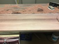
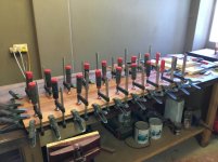
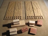
Assembly of the cabinets is progressing nicely. I've got the side panels laminated up from Jarrah and MDF, and have started cutting the interior bits up.
I've got a design roughed out for a simple active crossover (7 opamps), that I'll use eventually. In the short term I'll use a minidsp to prototype.
Assembly of the cabinets is progressing nicely. I've got the side panels laminated up from Jarrah and MDF, and have started cutting the interior bits up.
Attachments
I do however have a bunch of reasonably nice class AB lateral MOSFET amps
Oops, silly me, I forgot, and I followed that amp build avidly too.
Did you see Rod Elliott's 24dB active crossover?
I have seen Rod's crossover. It's good stuff, though I'm thinking baffle step correction and say 50us delay for the tweeter might help. In any case once I've prototyped the crossover with the minidsp I think I'll be in a better position to design something.
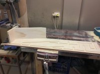
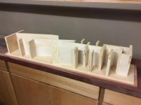
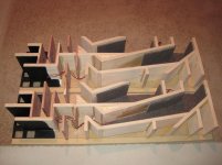
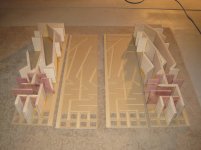
I spent the weekend cutting up bits of ply, and have done the guts for one speaker. It gets to be something of a challenge to line all the bits up and get the sides on - that'll teach me for aiming for an interference fit.
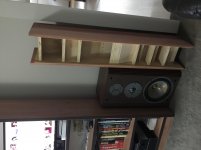
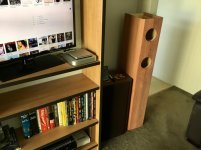
Anyway, an in-situ photo showing an in completed speaker next to one of my present infinity RS-5b. They're really rather tall! Even without the front and back, it's already heavy enough that I have to ask for Perry's help to move one.
I think the Jarrah will look quite the part.
I spent the weekend cutting up bits of ply, and have done the guts for one speaker. It gets to be something of a challenge to line all the bits up and get the sides on - that'll teach me for aiming for an interference fit.
Anyway, an in-situ photo showing an in completed speaker next to one of my present infinity RS-5b. They're really rather tall! Even without the front and back, it's already heavy enough that I have to ask for Perry's help to move one.
I think the Jarrah will look quite the part.
Attachments
Last edited:
Beautiful timber.I think the Jarrah will look quite the part.
I've got one cabinet to the point that it has a baffle. I'll have to make a new circle guide before I cut the hole for the tweeter. I didn't offset the woofers, as the suggested offset was small enough (1/8") that I reckon it'd just look like poor workmanship rather than deliberate, so the woofers are bang in the middle.
I've put a quick bevel on the sides - a few more goes with the plane will have that become a radius.
I have to admit I've got concerns as to whether the little P13WH drivers will be up to the job. I keep looking at other slightly larger mid-woofers (for example the SB acoustic SB17MFC35 - https://www.wagneronline.com.au/attachments/Audio-Speakers-PA/sbacoustics/SB17MFC35-8.pdf - which is 170mm across vs 140, but which I reckon I could squeeze in).
At this stage one side and the baffle are just pressed in place, so I can do the stuffing. I could conceivably build multiple baffles with different drivers and try them out.
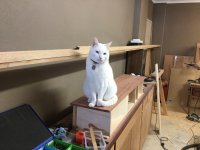
My cat isn't terribly impressed, as always when I'm working in the garage he has to be involved.
I've put a quick bevel on the sides - a few more goes with the plane will have that become a radius.
I have to admit I've got concerns as to whether the little P13WH drivers will be up to the job. I keep looking at other slightly larger mid-woofers (for example the SB acoustic SB17MFC35 - https://www.wagneronline.com.au/attachments/Audio-Speakers-PA/sbacoustics/SB17MFC35-8.pdf - which is 170mm across vs 140, but which I reckon I could squeeze in).
At this stage one side and the baffle are just pressed in place, so I can do the stuffing. I could conceivably build multiple baffles with different drivers and try them out.
My cat isn't terribly impressed, as always when I'm working in the garage he has to be involved.
Attachments
Last edited:
Much more bass but four times Vas.SB acoustic SB17MFC35
I have to admit I've got concerns as to whether the little P13WH drivers will be up to the job. I keep looking at other slightly larger mid-woofers (for example the SB acoustic SB17MFC35.
The P13 will be fine as there are 2 in parallel. This will give higher SPL and power handling, half the cone excursion, lower distortion. The 2 drivers have an Sd of 172cm² which is around that of a 7" driver and larger than that of the 18W8531 150cm² which is a 6.5" driver. I have no idea of the F3, F6 with the Ariel so have no idea whether it goes low enough for your needs. The lower octave can always be filled in with a subwoofer using a good woofer and not a subwoofer driver.
The SB17MFC35-8 is a great driver and I use it in a small floor standing main speaker that replaced my large mains. However, it wouldn't be a drop in for the Ariel as would need a complete redesign.
Nice build, BTW.
I'll have to make a new circle guide before I cut the hole for the tweeter.
I used a nylon breadboard as a circle jig for my router for a decade until I found this and wished I had it years ago.
Adjustable router guide
- Status
- This old topic is closed. If you want to reopen this topic, contact a moderator using the "Report Post" button.
- Home
- Loudspeakers
- Multi-Way
- Four Vifa p13wh00-08s and two Scan Speak d2905-950000