Hi To All,
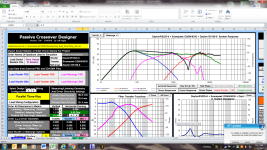
I have been designing a 3-way schematic in Xsim (screenshots attached). Also, I have been trying to gain experience in Passive Crossover Designer 7 using the same schematic. My question regarding polarity is why in Xsim do I only need to reverse polarity on the midrange but in PCD both midrange and tweeter need reverse polarity in order for summed response to be flat? (Screenshot of PCD is with tweeter positive polarity). Probably something that this novice is overlooking.") As always, any help is much appreciated!
As always, any help is much appreciated!
Best Regards,
Rich
I have been designing a 3-way schematic in Xsim (screenshots attached). Also, I have been trying to gain experience in Passive Crossover Designer 7 using the same schematic. My question regarding polarity is why in Xsim do I only need to reverse polarity on the midrange but in PCD both midrange and tweeter need reverse polarity in order for summed response to be flat? (Screenshot of PCD is with tweeter positive polarity). Probably something that this novice is overlooking.
As always, any help is much appreciated!Best Regards,
Rich
Attachments
Lojzek,
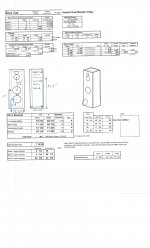
Thanks for the reply. I have attached Xsim file as you requested and another screenshot from PCD (hopefully better resolution). The delays in Xsim were .88 inches for woofer and .13 for tweeter. I arrived at those by measuring from cabinet to listening position and considering driver acoustic center differences. The design is a dual cabinet style similar Troels SB10. Upper Tweeter/Mid cab is sloped back 15 degrees. I'm hoping you can see all the information in the left hand side of PCD for driver sizes and offsets.
Best,
Rich
Attachments
Cal,
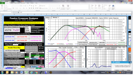
Thanks for the reply. Maybe its my lack of understanding the program then. I would think that it should only show a reverse null once polarity is flipped. The only way PCD summed response (black line) shows a flat line across is if both mid and tweeter are negative polarity. In Xsim, It is only the mid that requires negative polarity.
Best,
Rich
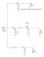
Hey Rich, everything seems to be working out fine once you turn off the vertical off-axis position of a mic to 0 deg in PCD and adapt the listening distance to long enough to match the XSim curve. I did change the position of the padding resistor 2,5R to be before the whole midrange filter in order to match the schematic of PCD and the difference between these is this. Also took the 0,1 uF out.
Attachments
Hey Rich, happy new year.
Just to follow up about your offsets:
Generally in each program you set the tweeter as your reference point. So in PCD "Relative Listening Height" and "Horizontal Panning" are generally relative to the tweeter axis. So if your tweeter is at ear height and the speakers are to be toed in towards your listening position, both would be set at 0.
For the y-axis in PCD (vertical driver offset), the tweeter is again usually set to 0 (especially if your data is actually from real measurements taken on the tweeter axis) and the mid and woofers get negative values. In XSim, you should note that there are no corresponding vertical offset values.
For the z-axis in PCD, it's the same thing - usually it's the mid and woofers that will have negative values when the tweeter is set to 0. With the values you've entered, you are actually telling the program that the tweeter's acoustic center is behind the mid's which should be incorrect unless you have the tweeter on a stepped baffle or in something like a recessed waveguide. In XSim, the driver offsets are positive values, but they will not be the same as the PCD values, they will be larger (except for the tweeters, which again should be 0 in both programs).
If I've figured things out correctly (not always the case, of course), your files are from real measurements so I'm going to perhaps suggest re-doing them and the acoustic center calculations repeatedly until you get consistent z offset results. You might try doing each woofer separately too. If you want to work in both PCD and XSim (which I think is actually a good idea) that means you'll need to go through the acoustic center process in each program. You can't just take the z values you get from PCD, change them to positive and use them in XSim.
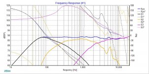
In terms of your xo, I might ask just a little less from your mid on the bottom end and a little more from the woofer. That should mean smaller values on a number of the relative components which can equate to some extra $ savings. Be good to know too if that 6000Hz peak on the mid is resonating. Either way, I might consider attenuating it anyways.
Also be sure to activate each driver's phase in the Summed Response in PCD - you want to be comparing those as well between the 2 programs.
Hope that helps.
Just to follow up about your offsets:
Generally in each program you set the tweeter as your reference point. So in PCD "Relative Listening Height" and "Horizontal Panning" are generally relative to the tweeter axis. So if your tweeter is at ear height and the speakers are to be toed in towards your listening position, both would be set at 0.
For the y-axis in PCD (vertical driver offset), the tweeter is again usually set to 0 (especially if your data is actually from real measurements taken on the tweeter axis) and the mid and woofers get negative values. In XSim, you should note that there are no corresponding vertical offset values.
For the z-axis in PCD, it's the same thing - usually it's the mid and woofers that will have negative values when the tweeter is set to 0. With the values you've entered, you are actually telling the program that the tweeter's acoustic center is behind the mid's which should be incorrect unless you have the tweeter on a stepped baffle or in something like a recessed waveguide. In XSim, the driver offsets are positive values, but they will not be the same as the PCD values, they will be larger (except for the tweeters, which again should be 0 in both programs).
If I've figured things out correctly (not always the case, of course
), your files are from real measurements so I'm going to perhaps suggest re-doing them and the acoustic center calculations repeatedly until you get consistent z offset results. You might try doing each woofer separately too. If you want to work in both PCD and XSim (which I think is actually a good idea) that means you'll need to go through the acoustic center process in each program. You can't just take the z values you get from PCD, change them to positive and use them in XSim.In terms of your xo, I might ask just a little less from your mid on the bottom end and a little more from the woofer. That should mean smaller values on a number of the relative components which can equate to some extra $ savings. Be good to know too if that 6000Hz peak on the mid is resonating. Either way, I might consider attenuating it anyways.
Also be sure to activate each driver's phase in the Summed Response in PCD - you want to be comparing those as well between the 2 programs.
Hope that helps.
Hi jReave, Happy New Year
Thanks a million for the very detailed and informative reply. Currently, I'm working with manufactures data (not actual measurements). My goals are to design these 3 way speakers with simulation tools as we did with the 2 way towers last year and then late this year take actual measurements. By the time these speakers are built, my environment for measuring will be way to noisy. My idea is to select lower cost passive XO items, knowing that adjustments down the road will probably be required. Also, by playing these speakers for several months may aid in more accurate measurements since drivers will be broken in.
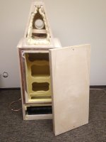
I have attached a photo of (1) of the speakers. As you can see, this is going to be a two cabinet sloped baffle for T/M design. Question: Do I still use the tweeter y axis as the reference even if it is behind mid range. Based on my measurements, the mid would be closest to the listener.
Measurements:
Mid= 82.5" (to listening position) + 1.125" driver offset= 83.625"
Tweeter= 83.75(" " ") 0 driver offset = 83.75"
Woofer(upper)= 82.875 (""") + 1.625 driver offset= 84.5"
As always, any help you can lend is much appreciated.
Best Regards,
Rich
Thanks a million for the very detailed and informative reply. Currently, I'm working with manufactures data (not actual measurements). My goals are to design these 3 way speakers with simulation tools as we did with the 2 way towers last year and then late this year take actual measurements. By the time these speakers are built, my environment for measuring will be way to noisy. My idea is to select lower cost passive XO items, knowing that adjustments down the road will probably be required. Also, by playing these speakers for several months may aid in more accurate measurements since drivers will be broken in.
I have attached a photo of (1) of the speakers. As you can see, this is going to be a two cabinet sloped baffle for T/M design. Question: Do I still use the tweeter y axis as the reference even if it is behind mid range. Based on my measurements, the mid would be closest to the listener.
Measurements:
Mid= 82.5" (to listening position) + 1.125" driver offset= 83.625"
Tweeter= 83.75(" " ") 0 driver offset = 83.75"
Woofer(upper)= 82.875 (""") + 1.625 driver offset= 84.5"
As always, any help you can lend is much appreciated.
Best Regards,
Rich
Attachments
Ah, a sloped baffle. I forgot to consider that case. Which makes things a little more complicated in terms of simulations only. In PCD, you can take this into account, but in XSim you cannot. Therefore, I would expect the 2 programs to give you slightly different results with PCD being the more accurate in terms of the tweeter's (and to a lesser extent the mid's) off-axis response.
So, should I assume from your data that your listening ear height is below the tweeter and more on-axis with the mid? And will this always be the case?
If you don't mind, I might like to play along with you again here. Can you attach a diagram showing the front dimensions and driver heights/spacing as well as one showing the side view? Also what will the listening height and distance be?
I haven't actually tried simming a sloped baffle before so other input is very welcome here, but I think that yes, I would still choose the tweeter height as my design axis and then proceed from there. I think that would be the way that I would measure them too when you get there - with the mike also at tweeter height. You would also therefore be correct right now to have the PCD listening height as off-axis although I'm not sure that 31.44* isn't just a little too much. However going with the mid as your design axis may work just as well. Personally I would probably try both setups and compare to see if there are any differences. But I really need to get the geometry right before proceeding.
Nice looking work on the cabinets btw. For the purposes of simming baffle diffraction, I can't quite tell, are you rounding or beveling any of the edges?
Hi jReave,
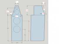
Awesome news! Really could use your expertise. I have attached a make shift boxy cad drawing, PCD 7 .csp worksheet, and Xsim file. I'm still a little uncertain of the geometry aspects that I have input. I agree tweeter should be the listening axis at 44 inches. That corresponds to my height sitting in a chair. Listening distance will be approximately 82.5 inches. There may be times when I will be seated at my desk off horizontal axis by approximately 30 degrees. So, it would be nice if we could design for solid off axis response. As for diffraction consideration, I'm looking at doing something very close to Sony SS-AR1 beveled edges as suggested by LineSource. You probably noticed the (3) laminated sheets of 18mm Baltic Birch to allow for the 45 degree angle bevel cuts. This will be the most nerve wrecking part of the entire build but I'm going large on this one area. Hopefully, I have supplied adequate information to get the ball rolling. Now things just got even more exciting knowing you are involved!
Best Regards,
Rich
Awesome news! Really could use your expertise.
I have attached a make shift boxy cad drawing, PCD 7 .csp worksheet, and Xsim file. I'm still a little uncertain of the geometry aspects that I have input. I agree tweeter should be the listening axis at 44 inches. That corresponds to my height sitting in a chair. Listening distance will be approximately 82.5 inches. There may be times when I will be seated at my desk off horizontal axis by approximately 30 degrees. So, it would be nice if we could design for solid off axis response. As for diffraction consideration, I'm looking at doing something very close to Sony SS-AR1 beveled edges as suggested by LineSource. You probably noticed the (3) laminated sheets of 18mm Baltic Birch to allow for the 45 degree angle bevel cuts. This will be the most nerve wrecking part of the entire build but I'm going large on this one area. Hopefully, I have supplied adequate information to get the ball rolling. Now things just got even more exciting knowing you are involved!Best Regards,
Rich
Attachments
Ok, that diagram helps but I was also looking for the values in the diagram below. Can you fill in the blanks? And is that the correct bottom cab width?
I must have missed your previous thread (or alas, I've already forgotten it) - beveled edges on the top cab? the bottom? or both?
I must have missed your previous thread (or alas, I've already forgotten it) - beveled edges on the top cab? the bottom? or both?
Attachments
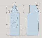
If you copy the image and then import it into MS Paint, you can easily change things around. To start off with, I made it in SketchUp. Alternatively, just do something like list the measurements from right to left and I'll see if I can't figure them out.
Ok, 1" and 1 1/2" bevels on top and bottom respectively. Got it. If I recall correctly, that top cab shape with a decent size bevel is particularly good at mitigating the hills and valleys of typical baffle edge diffraction. Darn hard to model correctly, but I'll give it a shot and tell you how I did it.
I'll just mention now that I'm glad to hear you will be eventually moving to real measurements because your design has a few things that are challenging to model correctly:
ie.
1) an odd cabinet shape with baffle edge treatment (the Edge will do the odd shape but doesn't calculate edge treatment, while the other 2 popular Excel diffraction prgrams will do edge treatment but can't quite handle all the details of your overall cabinet shape. The Baffle Diffraction Simulator may come the closest but it's got a steep learning curve. I'll try that and compare it with the Edge)
2) the sloping top baffle
3) and you've ported the mid when you have no real need to extend the LF's for that driver. Don't get rid of that though because stuffing the port to make it more or less aperiodic is considered by some (Troels for eg, I think) to be beneficial - it helps to lower the mid's impedance resonant peak which again is helpful for a mid in a 3-way. You can make a guess in terms of modeling but really the impedance needs to be properly measured with the driver in the box.
Hi jReave,
I figured it out. Thanks for pointing me in the right direction. Wanted to comment on ported mid. It is as you suspected and that is to serve as an aperiodic vent like Troels SB10 build. I modeled it in Unibox using Ql=3. Yea,
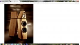
I do realize tools will ultimately be required. Also, I attached photo of Avalon Isis. That comes closest to the baffle design I'm looking for. Maybe top cab will be somewhat different but lower cab is what I would like to duplicate as much as possible.
Thanks Very Much,
Rich
I figured it out.
Thanks for pointing me in the right direction. Wanted to comment on ported mid. It is as you suspected and that is to serve as an aperiodic vent like Troels SB10 build. I modeled it in Unibox using Ql=3. Yea,I do realize tools will ultimately be required. Also, I attached photo of Avalon Isis. That comes closest to the baffle design I'm looking for. Maybe top cab will be somewhat different but lower cab is what I would like to duplicate as much as possible.
Thanks Very Much,
Rich
Attachments
Hi jReave,
I made a change to frd. file for mid in PCD and wanted to send you the lastest creation so we are on the same page moving forward. Also, I started changing a few XO values to arrive at a more downward FR slope as you suggested. I'm sure its going to be a work in progress.
Best,
Rich
I made a change to frd. file for mid in PCD and wanted to send you the lastest creation so we are on the same page moving forward. Also, I started changing a few XO values to arrive at a more downward FR slope as you suggested. I'm sure its going to be a work in progress.
Best,
Rich
Attachments
Just want to double check that you are using the paper RS 150 and not the older aluminum version.
Also curious if you have any reason for the Ql =3? Your are right to adjust it, just wondering how you arrived at that value. I haven't tried working with that variable before so I am completely clueless on this one.
I can't seem to convert either of those last 2 xo versions but I think things are going to change anyways.
I've just looked at the geometry of the sloped baffle and indeed the mid acoustic center looks to be ahead of the tweeter. What has surprised the heck out of me is that the same looks to be true for the woofer too. I didn't expect that.
Give me a day or so to work on things. I think I've figured out an easy way to work with the off-axis mid and tweeter FR's in XSim as well as PCD.
Btw, looks like you have really come along in terms of design - you've made some well though out decisions.
- Status
- This old topic is closed. If you want to reopen this topic, contact a moderator using the "Report Post" button.
- Home
- Loudspeakers
- Multi-Way
- Driver polarity Question