So today, after many hours spent building, I hooked up my speakers and to great frustration, discovered they are not playing music at normal loudness levels. Compared to my previous speakers using the same amp, the new speakers require about 80% power to match the loudness at 10% of the old pair. Something was clearly wrong.
I then bypassed the crossover and sent the audio directly to the drivers, the speakers now play music at expected loudness. This narrows the problem to the crossover I designed and built.
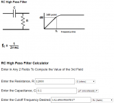
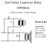
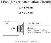
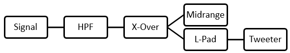
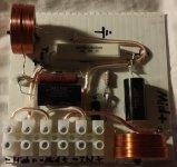
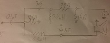
The circuit I built has 3 components implemented (by order): an C-R high pass filter (1st order butterworth, 130Hz), a two-way crossover (2nd order linkwitz-riley at 3250Hz) and an L-pad (3.25dB) for the tweeter. See attached pictures of individual circuits and combined circuit I built (tweeter polarity is reversed intentionally).
Info Summary:
I then bypassed the crossover and sent the audio directly to the drivers, the speakers now play music at expected loudness. This narrows the problem to the crossover I designed and built.
The circuit I built has 3 components implemented (by order): an C-R high pass filter (1st order butterworth, 130Hz), a two-way crossover (2nd order linkwitz-riley at 3250Hz) and an L-pad (3.25dB) for the tweeter. See attached pictures of individual circuits and combined circuit I built (tweeter polarity is reversed intentionally).
Info Summary:
- With crossover the speakers are ridiculously quiet and something is obviously not right
- With crossover both drivers do not play beyond cut-off frequencies, circuit is functioning properly in this sense
- With/without crossover, both drivers play clean music and the loudness is the same between drivers
Attachments
-
 Screenshot 2016-12-31 21.17.44.png28.4 KB · Views: 187
 -
 Screenshot 2016-12-31 18.36.23.png16.5 KB · Views: 179
 -
 Screenshot 2016-12-31 20.11.09.png16.5 KB · Views: 185
 -
 Screenshot 2016-12-31 21.41.02.png5.7 KB · Views: 166
 -
 2016-12-30 22.22.35.jpg839.1 KB · Views: 175
 -
 2016-12-31 21.45.15.jpg570.3 KB · Views: 118
Try bypassing the 100nF capacitor. It appears you are trying to high pass this system above 100Hz to use another woofer for bass? The problem is that your filter there is based on an impedance around 12k and it won't work as expected. The correct value to use will be closer to 12 ohms but will be based on a compromise. At the least you could remove the resistor as well, and replace the capacitor with something closer to 100uF.
Last edited:
The reason for the 12k resistor is to give the filter a fixed load to work into. As it happens, the speaker is overtaking this resistor in significance and the 100nF capacitor working into 8 ohms puts the high pass frequency well above the audio band, like a couple of hundred kHz.
See how it goes without a resistor (and with a better value of capacitor). If the irregular impedance of the speaker causes a response peak, there are a few ways to attend to it.
See how it goes without a resistor (and with a better value of capacitor). If the irregular impedance of the speaker causes a response peak, there are a few ways to attend to it.
Here are the drivers I am using which may help:
Mid-range:https://www.parts-express.com/peerless-by-tymphany-835024-5-1-4-aluminum-cone-hds-woofer--264-1076
Tweeter:https://www.parts-express.com/goldwood-gt-510-1-soft-dome-tweeter--270-176
Mid-range:https://www.parts-express.com/peerless-by-tymphany-835024-5-1-4-aluminum-cone-hds-woofer--264-1076
Tweeter:https://www.parts-express.com/goldwood-gt-510-1-soft-dome-tweeter--270-176
san1c99,
It's clear from your first post that you don't understand electronics math & this makes all your assumptions ( exercised within the first pic ), give wildly incorrect answers ( for your intended outcomes ).
( Even if those 2 drivers where 8 ohm actual resistors / which is just not the case ), your circuit impedance becomes just slightly less than 8 ohms ( when a 12K resistor is added in parallel to the network ).
As Allen has pointed out, you'll need a very large value capacitor HiPass ( for the 8 ohm load ) to give an effective roll-off below 130 hz.
")
PS; Read Allens ( stickied ) thread about how to design crossovers.
It's clear from your first post that you don't understand electronics math & this makes all your assumptions ( exercised within the first pic ), give wildly incorrect answers ( for your intended outcomes ).
( Even if those 2 drivers where 8 ohm actual resistors / which is just not the case ), your circuit impedance becomes just slightly less than 8 ohms ( when a 12K resistor is added in parallel to the network ).
As Allen has pointed out, you'll need a very large value capacitor HiPass ( for the 8 ohm load ) to give an effective roll-off below 130 hz.
PS; Read Allens ( stickied ) thread about how to design crossovers.
Last edited:
Ok so I believe I now understand where I went wrong.
I used an online calculator (im a newbie) to find the required resistance for the C-R HPF. I thought the given resistance value is only for the resistor placed in parallel (looking at the diagram above). Seems like it is actually the resistance of the entire circuit, my entire circuit resistance with the 12K ohm resistor in parallel is about 10 ohms. This means that the real cutoff frequency is actually 160,000Hz (yeah this is probably the issue).
I used an online calculator (im a newbie) to find the required resistance for the C-R HPF. I thought the given resistance value is only for the resistor placed in parallel (looking at the diagram above). Seems like it is actually the resistance of the entire circuit, my entire circuit resistance with the 12K ohm resistor in parallel is about 10 ohms. This means that the real cutoff frequency is actually 160,000Hz (yeah this is probably the issue).
Last edited:
Bingoit is actually the resistance of the entire circuit, my entire circuit resistance with the 12K ohm resistor in parallel is about 10 ohms.
I don't recommend it in this case. It can be done (I have done it and there are advantages), but it is tricky not to create problems. I think you'll have a better chance of success with a series capacitor. (option B would be a second order filter using one capacitor and one inductor).But it looks like I can rather make a cheap R-L HPF using a small 0.01 mH Inductor.
- Status
- This old topic is closed. If you want to reopen this topic, contact a moderator using the "Report Post" button.
- Home
- Loudspeakers
- Multi-Way
- Very very quiet speakers, crossover issue