Hi Guys,
I'm doing a school project (MFB woofer). Anyway, we're analyzing our measurements.
The blue signal is the input signal from the soundcard. The red signal is the recorded output signal from the woofer. The microphone is a Panasonic electret type as per Linkwitz.
I understand the ringing at the end is due to the resonance of the speaker. And I can clearly see the phase delay. However, what is causing the inital waveform to increase before decreasing (the spike at the beginning).
Thanks,
Pete
Attachments
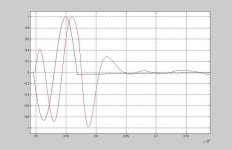
The connections are Soundcard to amplifier to speaker. The left input is taken from the soundcards output to input and the right is taken from the microphone in front of the speaker. The microphone is one of those panasonic electret types with a 9V bias and a non-inverting opamp (OPA227) with a gain of about 5.
I'm very confused.
Pete
I'm very confused.
Pete
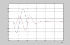
Nice, I think you might be right. Here's another graph. This is the first one we took, we thought the output was inverted so we changed it.
The odd thing here is that the speaker goes back towards the 0 position before the input. That's why we thought it was wrong.
Pete
The odd thing here is that the speaker goes back towards the 0 position before the input. That's why we thought it was wrong.
Pete
Attachments
Imagine you've just started pushing a really heavy weight on a swing, before you've pushed it as far as you want it to go, it starts heading backwards - that's the initial step at the start of the waveform. It makes it appear that the cone is anticipating the voltage waveform. Maybe try longer pulse to get a steadier output?
CM
CM
You said you were using a sound-card. Remember there is also a delay involved in the conversion (due to the FIR filters in the ADC and DAC)- this is typically ~48 samples (or 1ms at 48ksps). Then the windows drivers typically have input and output buffering which adds further delay. Not sure what it is but would be surprised if it was <20ms.
This is not a problem if you use one channel of ADC for reading back the voltage at the woofer, and the other from your feedback element.
As for the ringing- its probably not due to driver resonance as such. When you abruptly cut off a signal, you introduce a whole bunch of HF components (do an FFT on your signal and see). The woofer removes this HF information as it has a mechanical low-pass filter. The moving mass, and series inductance dominate the transfer function (Cone Velocity/Volts In) as frequency increases. If you pass your test signal through a 2nd order LPF (tuned to a few hundred Hz), you will see a similar effect on the time response.
Ok, I think I understand what you're saying.
Now we've hooked up the actual accelerometer that we'll be using for the testing.
It's 4 cycles of a 60Hz sine wave (input in blue, accelerometer output in red).
Same problems are evident. Anyway, the next plan is to develop the feedback/control network, which we're sort of stuck on.
Pete
Now we've hooked up the actual accelerometer that we'll be using for the testing.
It's 4 cycles of a 60Hz sine wave (input in blue, accelerometer output in red).
Same problems are evident. Anyway, the next plan is to develop the feedback/control network, which we're sort of stuck on.
Pete
Attachments
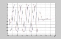
You want voltage feedback => cone velocity. You are measuring accelleration. This will result in the 90 degree phase shift you are seeing.
You need to pass the accelerometer output through an integrator to get velocity. That should line up pretty close to the original signal.
Most commercial approaches use multi-stage compensation to adjust the phase response of the loop to allow maximum open-loop gain, without the thing turning into a (very loud) siren. The more you wind up the accelerometer gain, the closer you will get to instability.
Any helpful comments? The lower you keep the frequencies, the easier it will be to control.
Chris Lockwood said:You want voltage feedback => cone velocity. You are measuring accelleration. This will result in the 90 degree phase shift you are seeing.
No. He wants cone acceleration, since sound pressure is proportional to the cone acceleration. If he had measured in the mass controlled regon, ie above the fs, he would (probably) have seen no phase shift. As I read the figure, the phase shift is near 90 degrees, so we should be near fs. What is the fs of the driver?
Voltage across the voice coil is proportional to voice-coil velocity. 
A microphone generates a voltage proportional to the velocity of its diaphragm.
Mounting an accellerometer on the diaphragm measures cone accelleration, not SPL.
If you use direct feedback of acceleration, the response will be that of an integrator- 6db/octave slope decreasing with frequency. Not ideal. Might (sort-of) compensate for baffle step though")
The Qes of the driver will determine the rate of phase shift either side of resonance. The lower the Q, the tighter the control of the amplifier, the slower the changes. Adding a negative resistance to the power amp (using some current feedback) can decrease the Q of the driver even more, and negate many of the effects of the mechanical parameters.
A microphone generates a voltage proportional to the velocity of its diaphragm.
Mounting an accellerometer on the diaphragm measures cone accelleration, not SPL.
If you use direct feedback of acceleration, the response will be that of an integrator- 6db/octave slope decreasing with frequency. Not ideal. Might (sort-of) compensate for baffle step though
The Qes of the driver will determine the rate of phase shift either side of resonance. The lower the Q, the tighter the control of the amplifier, the slower the changes. Adding a negative resistance to the power amp (using some current feedback) can decrease the Q of the driver even more, and negate many of the effects of the mechanical parameters.
Chris Lockwood said:Voltage across the voice coil is proportional to voice-coil velocity.
Sorry, no. Assuming you mean the loudspeaker (not the microphone, or measuring the velocity BMO an extra voice coil) the current flowing through the voice coil generates a force. In the mass-controlled frequency region, above fs, this force will generate an *acceleration*. F=ma, remember?. Now, since the respobnse above fs is essentially flat, neglecting baffle steps etc, this is one way of understanding that SP isproportional to cone *acceleration* not velocity.
Chris Lockwood said:
A microphone generates a voltage proportional to the velocity of its diaphragm.
Yes, and how does the velocity relate to the sound pressure? For the dynamic microphone they are proportional! But that is *not* because dynamic microphones behave like speakers, but because dynamic microphones work *around* the mechanical resonance, and in essence are *resistance* controlled within their useable frequency range. So here F=v*R. In the mass-controlled area (HF)the response curve starts to drop, and so it does in the spring-controlled area (LF). It is easy to imagine why dynamic microphones with a wide frequency range are rare.
The dynamic microphone works *around* its resonance, the dynamic speaker works *above* the resonance, and condenser microphones work *below* the resonance.
It might be easier if you play a step signal through the speaker, and the output will approximate an impulse ---> proof that the loudspeaker is a differentiator. What you are measuring with the microphone is the "rate of change of an acceleration signal". So to recover the input from the output, you need to integrate once.
An analogue integrator is simply an opamp with a capacitor for the negative feedback, and use a high value leakage resistor to stabilize it at DC. The resulting "integrated" signal can then be used as the negative feedback for the amplifier. You'll need to put some effort into RC filters and such-like to make the whole thing stable though.
CM
CeramicMan said:It might be easier if you play a step signal through the speaker, and the output will approximate an impulse ---> proof that the loudspeaker is a differentiator. What you are measuring with the microphone is the "rate of change of an acceleration signal". So to recover the input from the output, you need to integrate once.
CM
Hmmm. This seems like a "dangerous" way of thinking. I assume that you think of the sound you hear when connecting a battery or similar to the loudspeaker? In that case we do indeed hear a click sound. But the frequency content of this signal, and the timespan that we study, corresponds to far below system resonance fs. Take a square wave instead, of say 200 Hz (and fs=50Hz). The microphone signal will then be a square wave, ie no differentiation at all. Given that F=ma and F=I*Bl *in this frequency range* it is obvious that the cone acceleration is proportional to the applied current. Since the mic signal is square-shaped, the SP is proportional to acceleration.
The microphone does not measure the "rate of change of an acceleration signal" (what would that be, third derivative of position???), it measures sound pressure. But sound pressure is generated by the cone, or more specifically, its acceleration.
Do you have measurements that show otherwise?
- Status
- This old topic is closed. If you want to reopen this topic, contact a moderator using the "Report Post" button.
- Home
- Loudspeakers
- Multi-Way
- Transient Response Testing