You will find that even at 200Hz the recorded voltage will drop with time. Check out www.headphone.com for 100Hz square wave measurements of expensive headphones. The output will only be a DC step if the measurement is in a pressurized enclosed space rather than free-field, and even headphones don't fit the bill. Step input signals are often used because an impulse would need to be extremely loud before sufficient bass energy is recorded accurately and high frequencies may be distorted. With a perfect step input signal there is voltage and current, but no acceleration. On the other hand, even the air isn't perfect because a perfect speaker would generate a sonic boom.Svante said:
Hmmm. This seems like a "dangerous" way of thinking. I assume that you think of the sound you hear when connecting a battery or similar to the loudspeaker? In that case we do indeed hear a click sound. But the frequency content of this signal, and the timespan that we study, corresponds to far below system resonance fs. Take a square wave instead, of say 200 Hz (and fs=50Hz). The microphone signal will then be a square wave, ie no differentiation at all. Given that F=ma and F=I*Bl *in this frequency range* it is obvious that the cone acceleration is proportional to the applied current. Since the mic signal is square-shaped, the SP is proportional to acceleration.
The microphone does not measure the "rate of change of an acceleration signal" (what would that be, third derivative of position???), it measures sound pressure. But sound pressure is generated by the cone, or more specifically, its acceleration.
Do you have measurements that show otherwise?
CM
I tried this myself after posting the 200 Hz square wave thing. I also saw the drop, and IMO the explanation is that the speaker is not ideal, ie we are still close to the 50Hz cutoff, and there will be phase and small amplitude issues that distorts the square waveform.CeramicMan said:You will find that even at 200Hz the recorded voltage will drop with time.
Think of it a bit, how would a differentiated square wave look? You would see *impulses* at the slopes of the square wave, right? In fact this is similar to what you see if you lower the frequency *below* fs. A frequency of 1 Hz would certainly generate a impulse-like sound pressure (it will really be a differentiated impulse). As the frequency increases above fs, the waveform more and more approaches the same waveform as the input. So, as I said, in *the mass controlled* frequency range *above* fs, the SP waveform is essentially the same as the input current. The headphone is a completely different matter, since there is a closed cavity, and I would not want to add to the confusion by going into that. There will be a tilting of the FR because of the cavity, but let's stay at that.
I don't think I can explain this further, so if you are not convinced by this, let's leave it. There is no doubt in my mind that the sound pressure of a point source is proportional to the time derivative of its volume flow, and I don't think you can change that. Sorry.

Sorry, no. Assuming you mean the loudspeaker (not the microphone, or measuring the velocity BMO an extra voice coil) the current flowing through the voice coil generates a force. In the mass-controlled frequency region, above fs, this force will generate an *acceleration*. F=ma, remember?.
The impedance of the driver is non-resistive except at a point close to Fs. The resulting current in the voice coil is out of phase with the voltage across the voice coil (from the amplifier) for all other frequencies.
You are right that the input current is proportional to cone accelleration, but you need to be driving the speaker with a current amplifier (infinite output impedance). Almost ALL power amplifiers are set up as voltage sources (zero output impedance).
Another way to look at it...
Look at the transfer function of a loudspeaker describing acoustic output as a function of input signal, (you can find a good example on P25 of scholar.lib.vt.edu/theses/available/etd-120399-085715/ unrestricted/etd.pdf). This model correlates pretty closely with measured results, and is similar (identical?) to that derived by Richard Small.
The TF in terms of voltage has one common s term on the denominator => one zero at F=0 => one pure differentiation step.
The TF in terms of current has TWO common s terms on the denominator, implying that the input signal is differentiated twice before becoming the output signal.
The conclusion that we can draw from this is that with current drive, the result is an EXTRA differentiation step to the signal before it is translated into the acoustic pressure.
Voltage drive => cone velocity.
Current drive => cone accelleration.
This conclusion is based on working backward from the result of an involved derivation, but it is still valid due to the rules of LTI systems.
Svante, I think you're right. At low frequencies, well below the operating range of the speaker, yeah, the frequency response is approximately differentiated whereas I wrongly assumed that it will also be the case within its passband. I now belatedly realise that this must be wrong because differentiation and integration skews a flat frequency response by 6dB/octave, and speakers don't generally have such a response except in special cases.
Hmmm, lets say that the input to the speaker has a flat frequency response, and the speaker's output has a 6dB/oct bandpass response. The accelerometer will measure a high-pass frequency response with 3 gradients: 12dB/oct, 6dB/oct, and flat. Integrating this recovers the actual frequency response of the speaker (ie: the original band-pass response). If that is then used as negative feedback, there will be less feedback at very low frequencies and therefore increased gain where it is needed. Below a certain frequency the phase response should be locked together with the amplitude response and not cause instability. However, I think there are difficulties in making a practical circuit like this, because additional filtering is required to reduce the gain at high frequencies. A digital solution would be much better because steep and accurate filtering can be used, and problems with DC offsets could be solved more easily. Am I right?
CM
continuing...
....It's made trickier because there could be instability where the phase difference between input and output is more than 90 degrees, ie: anywhere the slope of the speaker's frequency response is greater than 6dB/octave. Even an oversized sealed box would be problematic, in which case an additional filter has to be added in after the input, such as one of Mr Linkwitz's subwoofer box compensation filters.
CM
Pure differentiators have a gain slope increasing to infinity as F goes up. What happens if you pump this into a 1st order low-pass filter?
The response flattens off around the cut-off frequency.
You no longer see that pure differentiation step, although it is still there! The zero at F=0 is still there, but its not immediately obvious from the frequency response plot unless you know how to look for it.
The transfer function is all you need to show that there are pure differentiations in both the current and voltage transfer function of a loudspeaker (differing by 1 order). The overall response characteristic is made up from the combination of room resistance, box dimensions, and mechanical, acoustical, and electrical properties of the driver. You dont see the pure differentiators in the frequency response plot because they are masked by the low-pass elements of the transfer function.
Hope that makes things clearer")
The response flattens off around the cut-off frequency.
You no longer see that pure differentiation step, although it is still there! The zero at F=0 is still there, but its not immediately obvious from the frequency response plot unless you know how to look for it.
The transfer function is all you need to show that there are pure differentiations in both the current and voltage transfer function of a loudspeaker (differing by 1 order). The overall response characteristic is made up from the combination of room resistance, box dimensions, and mechanical, acoustical, and electrical properties of the driver. You dont see the pure differentiators in the frequency response plot because they are masked by the low-pass elements of the transfer function.
Hope that makes things clearer
I think what confuses this is that we discuss *real* loudspeakers, when we should not ;-). This problem is a fundamental acoustic one. We have a source (=cone) and we want to regulate its motion such that the frequency response gets flat. We might measure the motion of the cone eg with an accelerometer. So what it all comes down to is the relation between cone acceleration and sound pressure. Voltages or currents to the speaker is only of secondary interest.
Looking in the textbooks I found the formula
p=(jwU*rho0)/(4*pi*r)
where U is the volume flow [m3/s], rho0 is the density of air [kg/m3] and r is the source-mic distance [m], and p is the sound pressure [Pa]. The equation is valid for free space. The multiplication with jw is equivalent to a differentiation, so the sound pressure from a point source is proportional to the derivative of the volume flow. The volume flow is proportional to the cone velocity, so the sound pressure is proportional to the cone acceleration. Period. Now, it does not matter *how* we make the cone move like we want, and if we have an accelerometer, its signal is an excellent candidate to be fed directly into the feedback loop since it is directly proportional to the sound pressure.
We don't have to involve how the dynamic speaker behaves, the whole idea with feedback is to compensate for that.
All the above assumes that the driver is mounted in a closed box.
Ok Svante, the thing with feedback loops is that they're picky about phase differences. If due to things like high-pass mechanical filtering the negative feedback is 91 degrees out of phase, then it is actually positive feedback and may cause instability of the amplifying system, depending on the gain. A subwoofer (midrange speakers would be an impossible challenge with accelerometer feedback) in a sealed box generally has a 2-pole high-pass transfer function, so the phase-shift approaches 180 degrees. Therefore this cannot be directly used as negative feedback without something that reduces the difference to under 90 degrees. Another integrator - but this time with a zero added near one of the pole frequencies - should do the trick!
What Pete has is a splendid little device that can measure the output of a speaker almost completely independently of room resonances, room gain and most ambient noises. In this application it is much better than an expensive microphone. I don't know how much it costs to use an anechoic chamber that's big enough to absorb 20Hz reflections, but it probably ain't cheap!
CM
CeramicMan said:Ok Svante, the thing with feedback loops is that they're picky about phase differences.
CM
Ok, I agree, some compensation would probably be needed to reach stability, but that should be done inside the feedback loop. The acceleration signal is still proportional to sound pressure, and that is what should be compared to the input voltage.
Svante,
We are just looking at the same problem from different perspectives, with different implementation methods.
We all agree that we are trying to control the cone accelleration. Loop stability is the big issue here. How much feedback we can apply is limited by the open-loop characteristic of the system, defined (in part) by the loudspeaker transfer function.
The perfect acceleration signal gain is constant with increasing frequency, with a zero phase with reference to the cone acceleration. However, there is delay in the system from the point we feed the power in (speaker terminals) to the cone. As frequency increases, the phase lag (from voice coil input voltage, to accelerometer output) will increase above 180 degrees with a *real* accellerometer.
Therefore to keep the system stable, we need to reduce the gain at high frequencies where our phase hits say 130 degrees to below the magic number 1.
OK so we all agree that we can put a low-pass filter on the output of the raw acceleration signal. This will satisfy the stability problem by reducing the gain where it counts, and give us some (limited) ability to correct distortion over the filter's passband range. Philips MFB from the late 70's does it this way, but it doesn't work *that* well at lower frequencies due to the relatively low amount of feedback that can be applied. The cut-off frequency of the filter determines the maximum amount of feedback that can be applied. The tradeoff is between bandwidth and distortion reduction with this technique.
Clearly it is quite easy to implement also, which is why it has been a popular technique.
Rather than using a low-pass filter, what if we use an integrator? The phase response is practically the same as a low-pass filter where it counts for stability (well into the LPF transition band). We get the added bonus of having increasing open loop gain with decreasing frequency which means increasing amounts of feedback, and more effective reduction in distortion where it counts.
What about the effect on closed loop response though? It becomes a differentiator, which is not what we want, but we CAN fix that by putting a nice clean electronic integrator on the input of the system to cancel that. Or we could apply some current feedback. This would allow adjustment of the system Q as well, so we can use drivers that might be better applied to feedback (high mechanical Q, high Bl), and fix the system Q with MFB.
Hang on, what if we just use velocity feedback instead of integrated acceleration? ITS THE SAME THING!!! You can either put an electronic integrator in front of the accellerometer, or use a device that measures cone velocity directly (eg bridge arrangement, or extra VC).
An accelerometer mounted on the cone with an integrator in series with it as its control loop filter is by definition VELOCITY FEEDBACK.
SO, we can either employ filtered acceleration feedback, with constant feedback in the low frequency range, or we can apply velocity feedback, with some form of extra compensation for the differentiating effect.
Ps
Sorry if I was misleading with my initial posts.
Some of it was wrong- especially the bit where I said "voltage across the voice-coil is proportional to velocity". This does not apply in general. The transfer function is anything but constant
Current on the other hand is closely proportional to acceleration (=>SPL) in the midband, controlled by compliance.
My brain was a bit rusty on this and I was a bit quick to respond...
Pardon if I miss the point - but isn't a square wave composed of (ideally) infinite high order harmonics? And isn't therefore a perfect step response limited by the inherent *LP* behavior of the speaker? And shouldn't the initial poster rather be testing using modulated tone bursts a la www.linkwitzlab.com ? Linkwitz has a lot of burst test info on his site (if it's still there after the recent pruning). His graphs look similar to the ones presented here.
MBK
MBK
Chris Lockwood said:Svante,
We are just looking at the same problem from different perspectives, with different implementation methods.
We all agree that we are trying to control the cone accelleration. Loop stability is the big issue here.
Yes, we are right!
For me the issue was the transfer function voltage -> sound pressure. But of course I would need stability as well, otherwise the transfer function would be pretty meaningless.
A step input has a frequency sprectrum that's sloped at 6dB/octave, and infinite harmonics like you said. By definition, an impulse response can be integrated to produce a step response, as a step response can be differentiated to form an impulse response. A modulated tone burst only tests a small range of frequencies with variable amplitudes, which is arguably less useful than testing all frequencies at once.MBK said:Pardon if I miss the point - but isn't a square wave composed of (ideally) infinite high order harmonics? And isn't therefore a perfect step response limited by the inherent *LP* behavior of the speaker? And shouldn't the initial poster rather be testing using modulated tone bursts a la www.linkwitzlab.com ? Linkwitz has a lot of burst test info on his site (if it's still there after the recent pruning). His graphs look similar to the ones presented here.
MBK
A step input is also very intuitive because even with inadequate analysis tools, a person can still learn a lot directly from the step "response" of the speaker. If the speaker is under-damped at a certain frequency, it means that at that frequency the total Q-factor is more than 0.707 and there will be ringing, and if it's less than 0.707 there won't be ringing. It's downright obvious that there's ringing if something that should be a nice curve has little ripples on it instead.
The downside of impulse response testing is that the amplitude has to be very high at high frequencies before anything measureable is recorded at low frequencies. Therefore, a step function can be used, which is then differentiated so the result is similar but with lower overall distortion.
The result is a graph with a little seismic ripple on it, and an FFT can be performed on the data. If all of the data is converted at once, a frequency response graph can be produced. If only a small snapshot of data is converted, only the frequency content at a particular section of time is known, and multiple snapshots of time are converted to create waterfall plots.
The speaker in question can be perfected if accurate sine and cosine frequency response data is gathered, and an FIR filter is generated that accurately flattens the frequency response.
Lech
MBK,
The problem is to create a functional MFB system. The MFB system is a feedback control system.
To solve this problem, we need a characterisation of the components in the system. If we assume that the system is approximately linear, and add some margin in our design to allow for the grossest of errors, we only need the frequency response of the system.
Specifically, we need the frequency response (magnitude and phase) of the accelerometer output with reference to the woofer input voltage.
The best way to measure this is the easiest way we can with the tools we have available, and assuming the feedback transducer is of high quality, we dont need to be too precise with our measurements. Sine wave continuous testing is good enough, using a signal generator and dual channel scope. We can measure the amplitude and phase for, say, 20 different frequencies, and join the dots on the graph.
Plenty of other methods are available, including impulse testing, MLS, and tone bursts- all have their advantages and disadvantages. USe what you have on hand. Remember, it only has to be done once
The plots alone will show a complex relationship. We use accurate models to identify the most predictable factors in the system. Measurements will give us the important variables (such as gain of the accelerometer).
If we already know the woofer mechanical characteristics (Bl, R, Mms, Cms, Rms), we plug it into the model and it should come up pretty close to what we measured. The remaining variable will be the accelerometer gain. This can be calculated by taking the mean of the magnitude response from measurements, and comparing to that of the predicted response.
We then take the model, and choose (or design from scratch) a control system configuration that suits it. Normally we might use current + velocity feedback, filtered acceleration feedback, or some other kind of arrangement...
The measurements will give us the *real* phase response, which tells us how much loop gain we can safely apply.
The feedback will then compensate for the deficiencies in the driver, AND all the approximations we made in our model. Remember, we left some margin in the design (normally the phase margin) to cater for the most gross of errors which might otherwise cause system instability.
Existing models for loudspeakers are very accurate in terms of predicted frequency response.
Once we have determined our control system layout, we then need to work out the maximum amount of feedback to apply before the system goes unstable. The easiest way is actually to build the system, and then do some final testing/adjustment.
With the loop open, we get a dual channel cro, and feed a signal generator into the system. The feedback point is compared to the input of the amplifier. (We need to include the accelerometer integrator or low-pass filter in this).
Wind the frequency up until the phase reaches approximately 135 degrees. Adjust the level of feedback until the input signal level matches the open loop feedback level.
Close the loop.
Now we have a nice phase margin and a low-distortion woofer!
Just add water...
Finally some results
Hi guys,
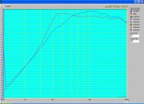
I finally got some positive results. I've spent a ton of hours to get this far however there are still many problems. I haven't been able to get it working with an integrator. Right now the accelerometer is being passed through a 2-pole low pass filter (sallen-key). I'm still having major phase issues. The bitmap attaches shows that the bandwidth is extended. This is really neat. However, the impulse response is worse than without the feedback and I can tell that the group delay is pretty bad.
Pete
Hi guys,
I finally got some positive results. I've spent a ton of hours to get this far however there are still many problems. I haven't been able to get it working with an integrator. Right now the accelerometer is being passed through a 2-pole low pass filter (sallen-key). I'm still having major phase issues. The bitmap attaches shows that the bandwidth is extended. This is really neat. However, the impulse response is worse than without the feedback and I can tell that the group delay is pretty bad.
Pete
Attachments
Re: Finally some results
For those of us who has been away from regulators for a while, could you post the structure (diagram) of your regulator?
cm961 said:Hi guys,
I finally got some positive results. I've spent a ton of hours to get this far however there are still many problems. I haven't been able to get it working with an integrator. Right now the accelerometer is being passed through a 2-pole low pass filter (sallen-key). I'm still having major phase issues. The bitmap attaches shows that the bandwidth is extended. This is really neat. However, the impulse response is worse than without the feedback and I can tell that the group delay is pretty bad.
Pete
For those of us who has been away from regulators for a while, could you post the structure (diagram) of your regulator?
ok i know i'm late on the post and i've seen somebody else mention this but you maybe having problems with your signals being lined up correctly
you've got one side going straight into your soundcard then the other going through an amp throught the speaker and then across the air gap to the mic and then into your soundcard
you need to delay the one that goes straight to your sound card and line them up first to get rid of the air gap (thats the one that delays the most) before you'll get any accurate results
try this on a fully working 30 day free demo
drawbacks on the demo - you cant save anything and it is only 30 days it writes something somewhere buried deep in your registery that prevents you reinstalling but then it is a $695 program used for setting up stadiums and the oscars of all things so you cant blame them
- Status
- This old topic is closed. If you want to reopen this topic, contact a moderator using the "Report Post" button.
- Home
- Loudspeakers
- Multi-Way
- Transient Response Testing