I've tried the paper cone SB and wasn't terribly impressed since IMO it needs the same attention given to the break up as a metal cone. So what's the point? And it's audible without, a dry hiss that is always present at low level.
Another very good candidate is a Scan Discovery.
augerpro,
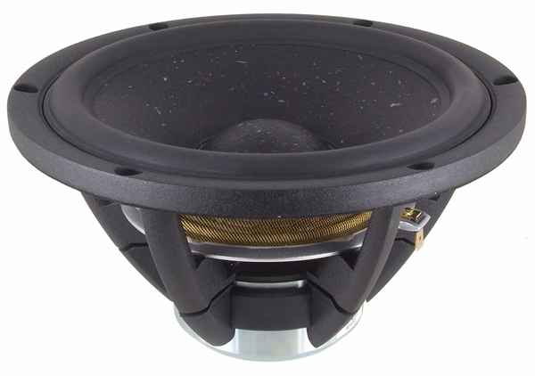
I have no experience with the SBA woofers. I noticed that there are two types of paper cone drivers from SBA in this range - one is the "coated" SB17NRXC35-8 and the other "uncoated" SB17NRXC35-8-UC. From what I have read (other speaker brands and models, not SBA), the coated cones are "quieter" vs the uncoated ones.
Which one of the paper coned SBA mid-bass did you try out?
Audio Gurman
There is a test of SB drivers on the russian website Audio Gurman.
??-????????, use a online translater if you are unable to read the native language.
There is a test of SB drivers on the russian website Audio Gurman.
??-????????, use a online translater if you are unable to read the native language.
Thanks for the tip Piersma. Audio terminology is universal so no translator needed to see 2H and 3H curves for. sB17NRXC35-4
The polycone SB17MFC35-4 is not as good:
The Satori MW16P-8 seems to have the lowest 3H distortion though (but higher euphonic 2H):
The 7in Revelator 18W/8351G00 looks very good:
The one I am really curious about is the 7.5in Satori MW19P-8:
An externally hosted image should be here but it was not working when we last tested it.
The polycone SB17MFC35-4 is not as good:
An externally hosted image should be here but it was not working when we last tested it.
The Satori MW16P-8 seems to have the lowest 3H distortion though (but higher euphonic 2H):
An externally hosted image should be here but it was not working when we last tested it.
The 7in Revelator 18W/8351G00 looks very good:
An externally hosted image should be here but it was not working when we last tested it.
The one I am really curious about is the 7.5in Satori MW19P-8:
Last edited:
augerpro,
I have no experience with the SBA woofers. I noticed that there are two types of paper cone drivers from SBA in this range - one is the "coated" SB17NRXC35-8 and the other "uncoated" SB17NRXC35-8-UC. From what I have read (other speaker brands and models, not SBA), the coated cones are "quieter" vs the uncoated ones.
Which one of the paper coned SBA mid-bass did you try out?
I used the coated paper. Also, these were the 15cm versions, which might behave a bit different than the 18cm ones that are being considered here.
The Wavecor stuff is very interesting, but they have so many different cone versions it's hard to figure out which to choose without buying them all and comparing.
Things have been slow but part of it is that I have actually just been enjoying this speaker as a two way active via miniDSP and two nice quasi-complementary MOSFET class AB amps.
I need to fix my 3d printer (clogged nozzle) and make the waveguide and baffle for the B80 mid.
Then take careful measurements, then have fun in Xsim or PCD for a while making the XO. Will probably pick back up this weekend.
I need to fix my 3d printer (clogged nozzle) and make the waveguide and baffle for the B80 mid.
Then take careful measurements, then have fun in Xsim or PCD for a while making the XO. Will probably pick back up this weekend.
Any progress yet? I'm also very interested to hear how you like the MDF enclosure vs the foam-core enclosures.
Things are still slow as work has picked up, we then had the holidays with family, then the printer nozzle is still clogged and now I am overseas on travel.
However, your question of how the MDF cabinet (with heavy sheets of Noico sound dampener, sound absorption foam, fiberglass fill) feels nice and weighs substantially more than the XPS foam cabinets used by the 10F/RS225 FAST speakers (with thin wood baffle), the distortion measurements are no better. Albeit, drivers are not identical - the XPS cabinet still has -45 to -50dB HD at similar music SPL levels (90dB at 0.5m). It will take more careful measurements of stored energy release etc. and maybe that is where it makes a difference.
Visaton B80 = Omnes Audio 3.5 ?
Decide for yourself:
https://www.oaudio.de/out/media/Datasheet_BB3_5.pdf
Test - technische Daten Lautsprecherchassis Breitbander - Visaton B 80 - 8 Ohm
http://www.visaton.com/bilder/fotos/gross/b80.jpg
https://www.oaudio.de/out/pictures/master/product/2/oaudiobb35.jpg
https://s1.postimg.org/47l02me8j3/ff80e92e.jpg
https://s1.postimg.org/21llguo2sf/oa3.5.png
It just might be that it is not that expensive to get to this level of performance. OmnesAudio from Germany is known for these kind of stunts. Here are Dayton RS225:
https://www.oaudio.de/en/Loudspeake...nesAudio/Woofer/Omnes-Audio-W8-Alu-Black.html
https://www.oaudio.de/en/Loudspeake...esAudio/Woofer/Omnes-Audio-W8-Alu-silver.html
Decide for yourself:
https://www.oaudio.de/out/media/Datasheet_BB3_5.pdf
Test - technische Daten Lautsprecherchassis Breitbander - Visaton B 80 - 8 Ohm
http://www.visaton.com/bilder/fotos/gross/b80.jpg
https://www.oaudio.de/out/pictures/master/product/2/oaudiobb35.jpg
An externally hosted image should be here but it was not working when we last tested it.
https://s1.postimg.org/47l02me8j3/ff80e92e.jpg
An externally hosted image should be here but it was not working when we last tested it.
https://s1.postimg.org/21llguo2sf/oa3.5.png
It just might be that it is not that expensive to get to this level of performance. OmnesAudio from Germany is known for these kind of stunts. Here are Dayton RS225:
https://www.oaudio.de/en/Loudspeake...nesAudio/Woofer/Omnes-Audio-W8-Alu-Black.html
https://www.oaudio.de/en/Loudspeake...esAudio/Woofer/Omnes-Audio-W8-Alu-silver.html
Last edited:
Things have been slow but part of it is that I have actually just been enjoying this speaker as a two way active via miniDSP and two nice quasi-complementary MOSFET class AB amps.
Bit gutted to see this spike at 1.8-2khz, as I wanted to use the 4 ohm.version with a ribbon. Will a 2nd order crossover @2.5khz suffice in reducing it?
(Keep in mind that we are bumping an old thread)Bit gutted to see this spike at 1.8-2khz, as I wanted to use the 4 ohm.version with a ribbon. Will a 2nd order crossover @2.5khz suffice in reducing it?
No, crossing at 2.5k won't really help reduce the HD spike on an RS180. Looking through this thread most posters seem to have an all too common misunderstanding on how HD trending works. The motor in a speaker is not completely linear so when you feed it a 2khz sinusoidal signal it does not move forwards and backwards in a perfectly sinusoidal motion. The motion is distorted non-linearly. A non-linear motion is described by multiple sinusoidal tones having a harmonic relationship. I.e. for a 2khz fundamental there will be 2k*2 = 4khz, 2k*3 = 6khz, 2k*4 = 8khz and so forth signals produced due to the non-linear motion. The phase and amplitude of these harmonics determine the shape of the distorted sine wave. A square wave signal for example is described by a sine fundamental and very strong odd order (3,5,7,9,etc) harmonics. Here is a good video of non-linear distortion in the time-domain and frequency-domain (start watching from 14:50) YouTube
The harmonic components produced by the motor get 'shaped' by the frequency response of the cone just like the fundamental does. That is why on a harmonic distortion plot the traces show the same breakup shapes as the fundamental but shifted down in frequency. What happens on a driver like the RS180 is that at 2khz, the 3rd harmonic which occurs at 6khz lands on the metal cone breakup - that is where the cone rings like a bell making the 6khz tone much louder. There will be the same problem at other frequencies which produce a harmonic tone at 6khz, for example at 1.2khz the 5th harmonic will be at 6khz.
Generally the harmonic distortion in speaker drivers is strongest for 2nd or 3rd, then 5th, then 4th, then 7th and then the remaining ones are pretty small/inaudible.
There are 3 methods to fix this problem.
Method 1: Avoid sending any loud stimulus to the driver at any frequencies which result in producing tones at the cone breakup peak. For the RS180 this means not sending 2khz signals to the driver to avoid the 3rd harmonic issue and not sending 1.2khz signals to the driver to avoid the 5th harmonic issue.
This means your lowpass filter must be considerably below this such that it has already rolled off by the problem frequencies! Generally 20-30dB is considered enough to make the problems inaudible. So if you crossed it to a 4th order lowpass slope at 500Hz, it would be over 24dB down by 1.2kHz, solving the issue almost completely.
Yes, this means that many woofers are only really suitable to be used in a high performance 3-way. Using them in a 2-way design results in a compromise on non-linear distortion performance compared to using a dedicated midrange in a 3-way design. It is up to the speaker designer to decide where and how steeply to cross the drivers to achieve the best compromise of overall performance. E.g. There is no point crossing the woofer very low if it then creates an issue for the mid/tweeter because it is not suited to crossing so low. Generally you would inspect a harmonic distortion plot for a given SPL and see at which point the harmonic curves cross over from one driver to the next (tweeter will be worsening towards lower freqs, woofer will be worsening towards the "breakup spike", therefore you pick a crossover frequency in the middle where both drivers are about the same in terms of HD).
Method 2 (likely impractical): Implement some means of physically/acoustically removing the 6kHz peak from the response. This could mean physically modifying the cone to change it's breakup behaviour, or placing the driver behind a filter which 'muffles' the 6kHz breakup peak - e.g. using a felt cover or a bandpass enclosure. No, implementing a notch filter at 6K in the crossover doesn't work because the generation of the harmonics at 6K and shaping by the cone breakup occurs at the speaker driver AFTER the crossover.
Method 3 (almost certainly impractical): Modify the motor of the driver to improve it's linearity so that harmonics are so small in amplitude to begin that the 'amplification' of the cone breakup is not enough to make them audible. Several drivers - notably many Scanspeak and SB Acoustics ones - have such brilliantly linear motor designs that even after 'amplification' by the cone breakup, harmonic distortion components are still well into the noise floor.
The exact same problem happens for drivers with other cone constructions. A paper cone for instance just spreads that 6khz breakup energy across a wider range of frequencies. So the breakup peak is not as big but it may start even earlier, perhaps 2 or 3khz instead of 6khz. So now on the paper driver the harmonic distortion will start to rise even earlier but not be as severe. The paper driver therefore might be considered a better compromise for a 2-way design, but for a 3-way where you intend to cross low the metal driver might be considered better because the harmonic distortion stays lower up to a higher frequency.
Last edited:
Quote
"Method 1: Avoid sending any loud stimulus to the driver at any frequencies which result in producing tones at the cone breakup peak. For the RS180 this means not sending 2khz signals to the driver to avoid the 3rd harmonic issue and not sending 1.2khz signals to the driver to avoid the 5th harmonic issue.
This means your lowpass filter must be considerably below this such that it has already rolled off by the problem frequencies! Generally 20-30dB is considered enough to make the problems inaudible. So if you crossed it to a 4th order lowpass slope at 500Hz, it would be over 24dB down by 1.2kHz, solving the issue almost completely."
Isnt that a bit overkill.. assumed that crossing just above would knock 3rd harmonic distortion down to at least an acceptable level.
Was thinking of this accuton build from a few years ago where the(well known) designer crossed the C90 cell pretty much at the point of offending spike
https://www.google.co.uk/url?sa=t&s...FjALegQIBRAB&usg=AOvVaw0H-Jx9lbtoejJ3UwZPr37P
https://www.google.co.uk/url?sa=t&s...iDQAQFggdMAE&usg=AOvVaw3V-VaHlqlqdj1xvqkDyPHj
Last edited:
Actually no it isn't overkill if your aim is to make the problem inaudible. In that accuton design they may not have really solved the problem - the midrange lowpass filter is only ~-10dB at the point of the 3rd harmonic spike. That said, in my opinion harmonics up at 10kHz+ are far less subjectively detectable than harmonics falling at frequencies <5kHz. YMMV.Isnt that a bit overkill.. assumed that crossing just above would knock 3rd harmonic distortion down to at least an acceptable level.
Was thinking of this accuton build from a few years ago where the(well known) designer crossed the C90 cell pretty much at the point of offending spike
https://www.google.co.uk/url?sa=t&s...FjALegQIBRAB&usg=AOvVaw0H-Jx9lbtoejJ3UwZPr37P
https://www.google.co.uk/url?sa=t&s...iDQAQFggdMAE&usg=AOvVaw3V-VaHlqlqdj1xvqkDyPHj
Take for example XRK's experience with the RS180. There was disappointment when it was seen that the 3rd harmonic at 2kHz was at -40dB relative to the fundamental. Before 'solving' this we have to first ask what is an acceptable level of HD. Lets say that we decide that 3rd order should be below -55dB everywhere. This means that the crossover filter on the RS180 must be -15dB at 2kHz, therefore bringing down the 3rd harmonic at 2kHz by 15dB to -55dB, meeting our requirement*. This would require a 2nd order electrical lowpass filter at ~750Hz or a 4th order electrical at ~1.2kHz. If you cross at 2.5kHz instead, you have only brought down the level at 2kHz by perhaps 2 or 3dB so the 3rd harmonic is still at -42 or -43dB.
The same logic has to be applied to any perceived problems on any of the other harmonic orders. Obviously if you are designing a 2-way you may have to compromise because the tweeter might not be up to crossing at 750Hz LR2 or 1.2KHz LR4. In that case you have to live with a non-linear distortion issue from the woofer, tweeter or both. Or go 3-way and find a midrange driver which can handle that region without a non-linear problem.
*In reality, the 3rd harmonic will probably fall by a little over 15dB when you do that because motors generally operate more linearly at lower sound levels. Perhaps the 3rd harmonic will now be at -60 or -65db instead of -55.
Last edited:
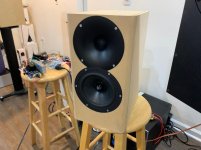
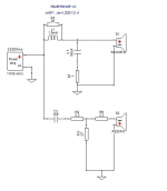
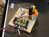
Hi folks, this project has stagnated for a while. I decided to make a quick passive crossover for a two way to get me going for fun. So I took some measurements and made a pretty simple crossover using XSim. I scrounged around my bench drawers and was able to cobble together a test crossover. Actually, the main cap is a 5uF polycarbonate - very good audio quality and inductor is decent too. The crossover measures well and although the tweeter is reversed polarity, the timing is very good.

XO design:

Yes, I know 1100Hz XO frequency. The waveguide seems to enable that. It’s still sounding clean.
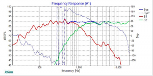
Predicted FR:

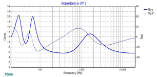
Predicted XO impedance:

Prototype XO:

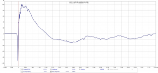
Measured speaker response:

Measured speaker step function:

I wonder if that small dip at 3500Hz is the cancellation reflection from the lip of the non flush rebate on the waveguide. It is about 1mm below flush. I could add a foam gasket to elevate it and see if it goes away. 3.5kHz is equal to 1.92in half wave distance.
XO design:
Yes, I know 1100Hz XO frequency. The waveguide seems to enable that. It’s still sounding clean.
Predicted FR:
Predicted XO impedance:
Prototype XO:
Measured speaker response:
Measured speaker step function:
I wonder if that small dip at 3500Hz is the cancellation reflection from the lip of the non flush rebate on the waveguide. It is about 1mm below flush. I could add a foam gasket to elevate it and see if it goes away. 3.5kHz is equal to 1.92in half wave distance.
Attachments
-
 9EF9020C-C0B3-4EB7-9D5B-E39C6636CEC3.jpg99.8 KB · Views: 3,198
 -
 5077BDA2-53A4-457E-AA4B-62509B2150AA.png62.1 KB · Views: 2,677
 -
 D679B570-3862-4A2A-95A4-E97814924CD2.png220.3 KB · Views: 478
 -
 FB30D045-3705-4CC9-982E-595853D179EF.png164 KB · Views: 458
 -
 35309888-C063-4C2C-AD8E-716BC91D01D7.jpg154.3 KB · Views: 478
 -
 57CA4515-09CF-4781-90D6-02A7DD28FE71.png329.3 KB · Views: 2,506
 -
 A8B3F670-6E2F-49B8-B881-4EAC56F2A1DF.png250.9 KB · Views: 1,848
Last edited:
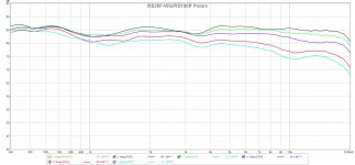
Checking performance of waveguide. Does appear to provide a nice wider angle of uniformity. Measured at 0.5m and 1.41Vrms. Angles approxiamted by eye so probably +/-3 deg.
Refresh your memory what the WG looks like - it was a Visaton unit modified to fit the RS28F with a 3d printed adapter plate.


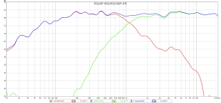
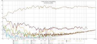
Here is harmonic distortion at 8 watts:

We can see some 3rd harmonic stuff from the RS180P start to rear its head around 300Hz to 800Hz range. But it is not noticeable at regular listening volumes of circa 82dB.
Refresh your memory what the WG looks like - it was a Visaton unit modified to fit the RS28F with a 3d printed adapter plate.
Here is harmonic distortion at 8 watts:
We can see some 3rd harmonic stuff from the RS180P start to rear its head around 300Hz to 800Hz range. But it is not noticeable at regular listening volumes of circa 82dB.
Attachments
Last edited:
- Status
- This old topic is closed. If you want to reopen this topic, contact a moderator using the "Report Post" button.
- Home
- Loudspeakers
- Multi-Way
- RS28F-RS180P-B80 as Hole Filler 3-way