Not sure I understand your point. Different bracing and damping methods are different by definition.Obviously they have spent a great amount of time and effort in figuring out all the details, but, besides the CLD braces, I don't really see a significant difference to any other bracing and damping methods.
The difference in effectiveness between competent extensional damping and competent constrained layer damping is substantial. The latter is a bit more involved but not a major task for DIY although determining a reasonably optimum damping material may take a bit of thought. But do you need the higher performance? Your cabinet is larger than the LS50 and with more radiating area and less stiffness for a given wall thickness and so it will be more of a challenge to make quiet.
Stiffening a low loss material like plywood or MDF with braces beyond a modest level will not make a cabinet quieter because it is not the physical mechanism that is limiting performance. This will be the low level of damping which needs increasing to increase the overall performance. So, for example, a 9-12mm inner structural layer, a 3 mm damping layer and a 4.5-6 mm constraining layer will give up some stiffness to gain high damping compared to a single 18mm structural layer. Adding some extensional damping to the 18mm structural layer will add some damping but a lot less than the CLD and so will not perform as well in terms of making the cabinet quieter. But will it perform well enough?
A damping layer between two braces connected to different panels is not really constrained layer damping because there is no constraining layer (which doesn't need to be connected to anything other than damping sheet in order to constrain). However, it will shear the damping material and so will be efficient so long as the panels move significantly relative to each other. To determine whether this is the case one really needs to know the mode shapes of the resonances that are to be damped. I suspect it might be tricky to get it to work well without this information.
Thank you for all your responses. I think I am starting to understand the difficulties of bracing and damping a little better now. I am going to redesign the cabinet a bit and post this here, but first I wanted to share a little experiment that I have done:
This is a very crude and simple experiment, but nevertheless, I think it does in a way relate to damping and bracing.
I happen to have a 1" × 1/4" × 10" flat piece of brass in my workshop which has a quite audible resonance when struck with a wooden stick.
So what I was trying to learn was, whether the brass bar, which would be a wood panel in a speaker, would ring significantly less when braced with some kind of viscoelastic layer. Well, it did.
This is a very crude and simple experiment, but nevertheless, I think it does in a way relate to damping and bracing.
I happen to have a 1" × 1/4" × 10" flat piece of brass in my workshop which has a quite audible resonance when struck with a wooden stick.
1)
I used a metal C-Clamp and clamped the brass bar at the end and struck it, observing the resonance (ringing).
2)
Then I used the same C-Clamp and clamped the brass bar at the center, stuck the brass bar at its end and observed the resonance again.
3)
Then I mounted the C-Clamp at the end of the brass bar again, but this time I used a 1/8" layer of cork between the jars of the clamp.
4)
Lastly I mounted the brass bar again at the center, but with the 1/8" layer of cork between the jars.
The results were pretty impressive.I used a metal C-Clamp and clamped the brass bar at the end and struck it, observing the resonance (ringing).
2)
Then I used the same C-Clamp and clamped the brass bar at the center, stuck the brass bar at its end and observed the resonance again.
3)
Then I mounted the C-Clamp at the end of the brass bar again, but this time I used a 1/8" layer of cork between the jars of the clamp.
4)
Lastly I mounted the brass bar again at the center, but with the 1/8" layer of cork between the jars.
1) I could hear a dominant ringing, it was quite strong, I actually could even feel it in my hand at the C-Clamp.
2) This reduced the apparent ringing "loudness", but the ringing was clearly at a higher frequency now.
3) This significantly reduced the ringing. I could barely hear the sound of the brass bar anymore.
4) The result was similar to 3), with a higher pitched "thug" sound, but pretty much at the same loudness.
Of course I understand that this was an extremely crude experiment, but despite the un-scientific nature of this test, the differences were quite obvious.2) This reduced the apparent ringing "loudness", but the ringing was clearly at a higher frequency now.
3) This significantly reduced the ringing. I could barely hear the sound of the brass bar anymore.
4) The result was similar to 3), with a higher pitched "thug" sound, but pretty much at the same loudness.
So what I was trying to learn was, whether the brass bar, which would be a wood panel in a speaker, would ring significantly less when braced with some kind of viscoelastic layer. Well, it did.
@drtebi
you may try to replace the cork layer in your experiments by e.g. dense felt, bituminized roofing, etc. ...
Cork is a material still flexing a lot (acting spring like, rubber like) and is not very "plastic" (lossy). Although it may show some positive effects in such configurations. I also know cork quite well and use it for decoupling sometimes, but i think it is not the best for use as dampening layer.
However, to damp structure born sound in machine housings etc. often "gap dampening" is used, having a gap between layers or adjoining segments that is filled with lossy material. Also a "constraint layer" is a method of damping vibrations of walls.
Fine and dry sand may also be an interesting material, that can provide mass and damping, if a hollow structure is filled with it.
Here some guys were testing different kinds of sandwich materials, trying to get "silent as possible" walls :
http://www.waveguide-audio.de/bitumen-sandwich-gegen-plattenresonanzen.html
http://www.picosound.de/D_gehmat.htm
Last edited:
OK, so how about this to start with:
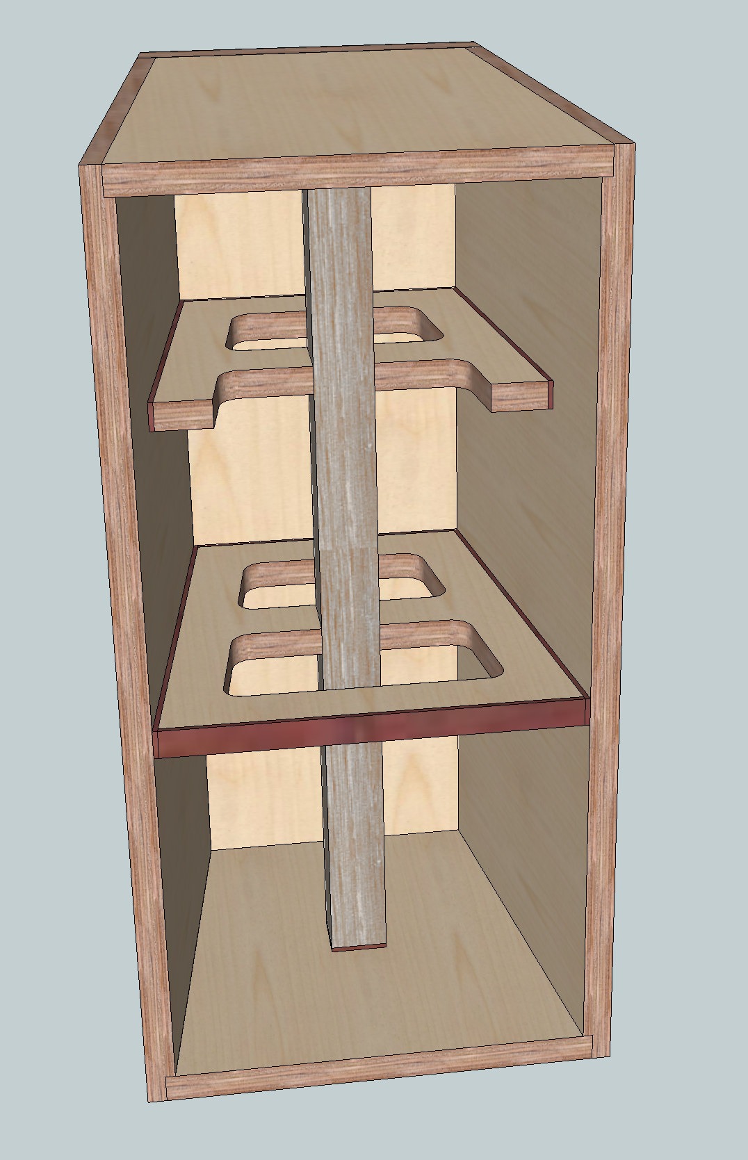
I have reduced the braces to two braces. The edges of the braces are "lined", or "edge banded" with a viscous material of 1/8" thickness (not sure which material to use yet, I suppose rubber would work, bitumen etc.). This would essentially be what the KEF LS50 has done with the "CLD braces".
Additionally I have added a 1.5" x 1.5" oak brace running from top to bottom, which is rigidly attached to the horizontal braces. The oak brace should have the same viscous material lining at its ends.
I initially wanted to make a "double" front baffle anyway; so I suppose I could sandwich a layer of viscous material in between this double baffle as well for further decoupling.
Does this make any sense at all?
I initially wanted to make a "double" front baffle anyway; so I suppose I could sandwich a layer of viscous material in between this double baffle as well for further decoupling.
Sorbothane.
32 litres.. even for the 'stepchild' 10 " Tannoy' is wayyy too small.
10's.. even in the Alnico version had a Goofy condition where the Voice coil was 2.5" diameter Yet the HF unit was 2" (typical size for ALL other DC's)
the resultant Big mismatch there caused all manner of odd sound effects.
As for Boxes..Triple the volume before you have a speaker worthy of the name Tannoy.
Last edited:
Not really. If you want a brace to stiffen the structure then it cannot have a soft edge/joint because that weak joint will determine the overall stiffness of the strut. Damping material is relatively weak and most materials work a lot better in shear than they do in extension/compression and so to be effective it needs to be applied to a lot of area and preferably sheared. So your vertical strut, for example, should be two wide and thin struts with damping material between them and one glued to the top wall and one glued to the bottom. The position on the walls is important because you want the relative motion between them to be large. If both walls were to move a lot but together in the same direction that would not be much good. Such a "strut" will not stiffen the structure to any extent but it will damp the relative motion between the two walls.Does this make any sense at all?
This is for a coaxial driver (Tannoy DC 2528), with a crossover at 1.5 kHz.
The enclosure is supposed to be sealed and filled with polyfill, inner volume
is about 32.5 liters.
Assuming TS parameters Fs=25; Qts=0,25 and Vas=240 lit are correct enough,
without EQ of the low end, the bass will roll off very early. Ported box would
be a lot better in a larger volume, naturally.
I see people are giving you enough hard time with bracing and damping, so I
won't add more to it.
I am aware of that. But the speakers will be in "8 pi", corner positions. A wall behind and next to each one, and on top of a desk... I calculated the room boundary and room gain, which would raise up the lower frequency response quite a bit, and hopefully (theoretically?) leveling it out.Assuming TS parameters Fs=25; Qts=0,25 and Vas=240 lit are correct enough,
without EQ of the low end, the bass will roll off very early. Ported box would
be a lot better in a larger volume, naturally.
I see people are giving you enough hard time with bracing and damping, so I
won't add more to it.
Not all Tannoy drivers are the same.32 litres.. even for the 'stepchild' 10 " Tannoy' is wayyy too small.
10's.. even in the Alnico version had a Goofy condition where the Voice coil was 2.5" diameter Yet the HF unit was 2" (typical size for ALL other DC's)
the resultant Big mismatch there caused all manner of odd sound effects.
As for Boxes..Triple the volume before you have a speaker worthy of the name Tannoy.
Thiele parameters for the DC 2528:
Voice coil resistance, Re: 5,8 ohm
Free air resonant frequency, fs: 26 Hz
Moving mass, Mms: 34,4 gm
Electrical Q, Qes: 0,26 -
Mechanical & Acoustical Q, Qms: 2,2 -
Total Q, Qts: 0,23 -
Force factor, Bl: 11,2 N/A
Total suspension compliance, Cms: 1,1 mm/N
Equivalent volume compliance, Vas: 200 Litre
Mechanical resistance, Rms: 2,55 Mechanical ohm
Effective radiating area, Sd: 360 sq. cm
Sensitivity (2.83V@1m, 20 deg. C): 91,2 dB
Unibox recommends for a sealed enclosure: 21.3 litersFree air resonant frequency, fs: 26 Hz
Moving mass, Mms: 34,4 gm
Electrical Q, Qes: 0,26 -
Mechanical & Acoustical Q, Qms: 2,2 -
Total Q, Qts: 0,23 -
Force factor, Bl: 11,2 N/A
Total suspension compliance, Cms: 1,1 mm/N
Equivalent volume compliance, Vas: 200 Litre
Mechanical resistance, Rms: 2,55 Mechanical ohm
Effective radiating area, Sd: 360 sq. cm
Sensitivity (2.83V@1m, 20 deg. C): 91,2 dB
Unibox recommends for a bass reflex enclosure: 35.9 liters
Tannoy itself put this very driver into:
T225 Mayfair using 2528 Dual Concentric with 2500 ABR (76.6 liters)
T185 Dorset using 2528 Dual Concentric with 2500 ABR (71.4 liters)
T165 Chester using 2528 Dual Concentric (49 liters)
T145 Ascot using 2528 Dual Concentric (40 liters)
T185 Dorset using 2528 Dual Concentric with 2500 ABR (71.4 liters)
T165 Chester using 2528 Dual Concentric (49 liters)
T145 Ascot using 2528 Dual Concentric (40 liters)
I am sorry, but I have a hard time following your suggestions.Not really. If you want a brace to stiffen the structure then it cannot have a soft edge/joint because that weak joint will determine the overall stiffness of the strut. Damping material is relatively weak and most materials work a lot better in shear than they do in extension/compression and so to be effective it needs to be applied to a lot of area and preferably sheared. So your vertical strut, for example, should be two wide and thin struts with damping material between them and one glued to the top wall and one glued to the bottom. The position on the walls is important because you want the relative motion between them to be large. If both walls were to move a lot but together in the same direction that would not be much good. Such a "strut" will not stiffen the structure to any extent but it will damp the relative motion between the two walls.
Please also remember that this enclosure is not particularly large (about 32 liters vB). Exterior dimensions are about 12 × 24 × 11 (W × H × D).
Where would you put braces, and where would you add damping?
I want to use the original crossover to start with and do some measurements with those. The drivers and xover come from the "Dorset" speakers.Will you be building test cabinets to see how it goes with
room augmentation? What XO filter do you plan to use?
Since these go onto my desk, I am a bit limited in how large they can be. 32 liters is already pushing it a bit...
My idea was to keep the option open to convert them to bass reflex enclosures should I not like the sealed enclosure result. As mentioned, Unibox recommends a 21.3 liter sealed enclosure (Qtc 0.707), and 35.9 liter bass reflex.
Not as far as I know.Thanks, is this Dorset XO filter schematic anywhere to be found for free.
Just being curious.
I was only able to find one forum post where someone else build a transmission line with the DC 2528:
Tannoy DC2528 Transmission Line build.
Images are dead, but you can find cached images here:
Tannoy TL Images
Crossover frequency of the original xover is 1.5 kHz.
Those are very interesting experiments (I speak German, which made it easier to understand ☺).@drtebi
you may try to replace the cork layer in your experiments by e.g. dense felt, bituminized roofing, etc. ...
Cork is a material still flexing a lot (acting spring like, rubber like) and is not very "plastic" (lossy). Although it may show some positive effects in such configurations. I also know cork quite well and use it for decoupling sometimes, but i think it is not the best for use as dampening layer.
However, to damp structure born sound in machine housings etc. often "gap dampening" is used, having a gap between layers or adjoining segments that is filled with lossy material. Also a "constraint layer" is a method of damping vibrations of walls.
Fine and dry sand may also be an interesting material, that can provide mass and damping, if a hollow structure is filled with it.
Here some guys were testing different kinds of sandwich materials, trying to get "silent as possible" walls :
Bitumen Sandwich gegen Plattenresonanzen - waveguide-audio
HAUPT
It looks like Butyl is another damping layer often used in CLD. I am thinking whether it may make sense to use a Butyl layer in between my double baffle...
Where would you put braces, and where would you add damping?
I think you've got hard time following because you want to make the brace in the Kef ls 50 way, but without extensive analysis this is not going to be easily predictable.
An other way to do this is to do bracing in first place, then to think about some kind of cld.
Take a look at post 12 in this thread, Andy linked some pictures of loudspeaker box done like this: you have a first inner box with bracing and for cld then some 'black material' put all around the inner box and a second outer shell.
From what i've seen in the picture the inner box wall are thicker then the outer ones and the intermediate black material layer is approx 1/4 the thickness of the bigger wall.
You could do more or less the same using MDF or BB multiply and some kind of bitumen or sorbhotane sandwich.
You'll need to perform some test to see if material choosen (thickness and type of material for each layer of the sandwich and how they interact) are ok with what you are trying to achieve.
You could get inspiration from here for cld:
http://www.diyaudio.com/forums/mult...e-aligned-constrained-layer-construction.html
For bracing follow advice already given: brace every 10cm at max and make the brace to be in contact with each wall and if possible the rear of the driver (to help dissipating energy on the whole inner box strucure rather than only the front face where drivers are hanging).
Last edited:
Chortle. You seem determined that every modification to your original design makes things worse. The baffle wants to be stiff so that it bends as little as possible when the driver hammers away at it. If you put a soft damping material between two stiff materials then it is only the inner layer that will resist being bent by the driver. The soft damping layer will be squashed by the inner layer but in squashing it will only push weakly on the outer layer. If the outer layer is only there as a constraint to help deform the damping layer that is fine but if you want it add stiffness/strength which you probably do for a front baffle then it won't to any significant extent.It looks like Butyl is another damping layer often used in CLD. I am thinking whether it may make sense to use a Butyl layer in between my double baffle...
Where would you put braces, and where would you add damping?
As mentioned earlier and shown in the section of the commercial AE speaker I would probably use something like a box of 12mm ply, 3mm stiffish damping material, 6mm constraining layer. I would stiffen the front baffle by perhaps sticking another 12mm layer to the inside. I would add a few braces in all 3 directions and glue them together where they crossed guided by FE simulations of what I was doing. Without the FE simulations I would guess at something like a slightly irregular 3d lattice with around 1 to 3 rows of struts in each direction. I would only consider a pair of "damping struts" of the type described in the previous post if there was a known problem to address but I wouldn't expect one if CLD is used for the main box.
Note this is only a rough outline because it takes time to work through a design and see what works as intended, what doesn't, fix/improve what doesn't and repeat... This needs to be quantitative either via measurement or more efficiently via simulations because you need to know how much is required to get the job done. For example, your original design using thin layers of extensional damping would introduce some damping. How do you know if it enough, if is nearly enough and doubling the thickness would do it or that faffing around with CLD is going to be necessary?
Thank you. That all sounds very reasonable. More in my next reply...I think you've got hard time following because you want to make the brace in the Kef ls 50 way, but without extensive analysis this is not going to be easily predictable.
An other way to do this is to do bracing in first place, then to think about some kind of cld.
Take a look at post 12 in this thread, Andy linked some pictures of loudspeaker box done like this: you have a first inner box with bracing and for cld then some 'black material' put all around the inner box and a second outer shell.
From what i've seen in the picture the inner box wall are thicker then the outer ones and the intermediate black material layer is approx 1/4 the thickness of the bigger wall.
You could do more or less the same using MDF or BB multiply and some kind of bitumen or sorbhotane sandwich.
You'll need to perform some test to see if material choosen (thickness and type of material for each layer of the sandwich and how they interact) are ok with what you are trying to achieve.
You could get inspiration from here for cld:
http://www.diyaudio.com/forums/mult...e-aligned-constrained-layer-construction.html
For bracing follow advice already given: brace every 10cm at max and make the brace to be in contact with each wall and if possible the rear of the driver (to help dissipating energy on the whole inner box strucure rather than only the front face where drivers are hanging).
It looks like Butyl is another damping layer often used in CLD. I am thinking whether it may make sense to use a Butyl layer in between my double baffle...
That's what I did on my double aluminium baffle. Butyl is available in rope shape and tape-like shape as well. My baffle is quite narrow so I used the butyl rope.
It has a couple advantages compared to bitumen products, no odour being one of them
") . Easily available as it's used for several purposes in the automobile industry.
. Easily available as it's used for several purposes in the automobile industry.Attachments
- Status
- This old topic is closed. If you want to reopen this topic, contact a moderator using the "Report Post" button.
- Home
- Loudspeakers
- Multi-Way
- To damp or not to damp sealed enclosure, still confused!