Hi!
I've just came across this website:
Impedance Coupled Bass is the next logical step in transmission line design
Apparently it is a kind of transmission line enclosure, with a special bass loading below driver resonance frequency.
They claim 35 Hz low-end response from 5" midwoofers....
Anyone have any idea about what it is, a simple marketing hoax, or is it really working? And if yes, how?

Hi,
Its easy to spot advanced nonsense, it doesn't make any sense.
I wouldn't trust anyone that produced this pile of garbage :
Meadowlark Swift loudspeaker The Review | Stereophile.com
rgds, sreten.
Its easy to spot advanced nonsense, it doesn't make any sense.
I wouldn't trust anyone that produced this pile of garbage :
Meadowlark Swift loudspeaker The Review | Stereophile.com
rgds, sreten.
Hi,
Its easy to spot advanced nonsense
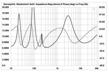
I would agree. They should back it up with impedance measurements.
(the Stereophile imp plot doesn’t show any particular acoustic loading at low freq)
this pile of garbage :
Don’t fall on the same trap. Please be specific.
George

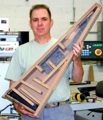
I think what they are doing is resistively damping the airflow through the port using denser foam at the terminus - note the dark piece of foam squeezed into the bottom of the line in the first picture in post #2. This would tend to reduce cone flap below line resonance.
I've used the same technique in my own Tannoy tapered transmission line speakers. By carefully selecting the thickness and density of foam blocks fitted into the open end of the line I've been able to tailor the lowest frequency response to match room characteristics. Ok, it may not be traditional transmission line practice but it's very effective and a hell of a lot easier than adjusting the stuffing density of the whole line. It's also good for keeping the moths out of the stuffing!
I've used the same technique in my own Tannoy tapered transmission line speakers. By carefully selecting the thickness and density of foam blocks fitted into the open end of the line I've been able to tailor the lowest frequency response to match room characteristics. Ok, it may not be traditional transmission line practice but it's very effective and a hell of a lot easier than adjusting the stuffing density of the whole line. It's also good for keeping the moths out of the stuffing!
Wouldn't it make sense to place a flow resistance close to the driver because this way the motion could be controlled below resonance (and above !) ? At the line's resonance the flow resistance would only show a minor effect because it is placed at a pressure node in this case. Depending on its length the flow resistance could be effective over a wider range above the line resonance as well.
It would be important though to have a flow resistance that doesn't show hysteretic behaviour of course.
Regards
Charles
It would be important though to have a flow resistance that doesn't show hysteretic behaviour of course.
Regards
Charles
A good question, in my case it was a matter of physical expediency rather than TL theory (I can't speak for the speakers the OP referenced). I have large drivers (HPD315s) and being low Qts I used a large taper (around 10:1). The line is already well stuffed, including the area around the driver, additional damping at this point would be difficult.
I was working on the basis that below line resonance, the line is acting as a pipe (exhaust pipe if you like) with greatest air velocity at the port (the narrowest section). My reasoning is that airflow restriction here has the greatest effect on the driver below Fs with least effect on higher frequencies, where the line works well anyway.
Hysteretic behaviour in the damping is important, yes. I experimented with various foam types and thicknesses before settling on a fairly rigid type (cuts with a razor blade without deformation).
Regards,
Chris
Last edited:
- Status
- This old topic is closed. If you want to reopen this topic, contact a moderator using the "Report Post" button.
- Home
- Loudspeakers
- Multi-Way
- Impedance coupled bass