Test baffle done
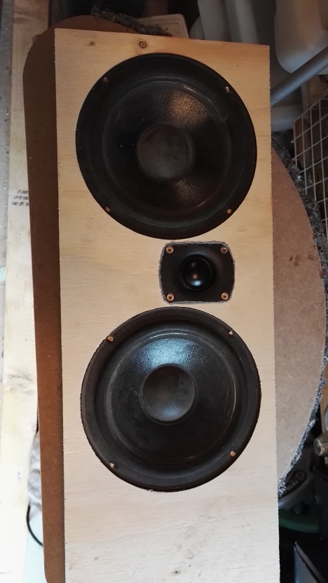
Alright, so now I've made a test baffle that is correct width and includes both woofers:
I did a simulation of the measured parameters and got this for a ported box in hornresp:
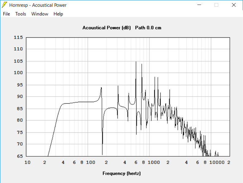 Result in 4 x Pi, 2.83 V. It's a 29 l ported box that is 120 cm high. I seem to get about 91 dB before reaching 2 mm diaphragm displacement which I'm guessing is around xmax.
/Anton
Alright, so now I've made a test baffle that is correct width and includes both woofers:
I did a simulation of the measured parameters and got this for a ported box in hornresp:
/Anton
Attachments


We've seen this sort of thing before, here using a less efficient 90dB tweeter:
Vifa PL14WJ-
The tweeter is a 4 ohm and its about 94dB:
https://www.madisoundspeakerstore.com/vifa-soft-dome-tweeters/vifa-bc25sc55-04-1-textile-dome-tweeter-truncated/
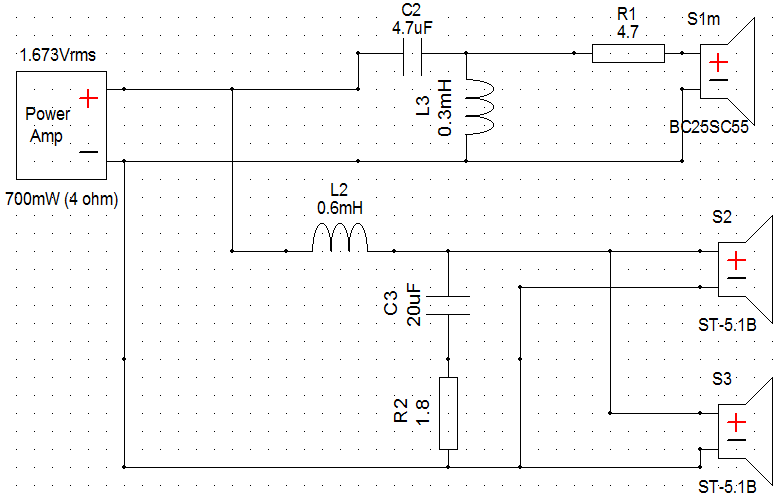
If you want simple, the below would be about right. Adjust red resistor for level. A 4.7R might be about right, but that is always select to taste.
Vifa PL14WJ-
The tweeter is a 4 ohm and its about 94dB:
https://www.madisoundspeakerstore.com/vifa-soft-dome-tweeters/vifa-bc25sc55-04-1-textile-dome-tweeter-truncated/
If you want simple, the below would be about right. Adjust red resistor for level. A 4.7R might be about right, but that is always select to taste.
Attachments

New measurements
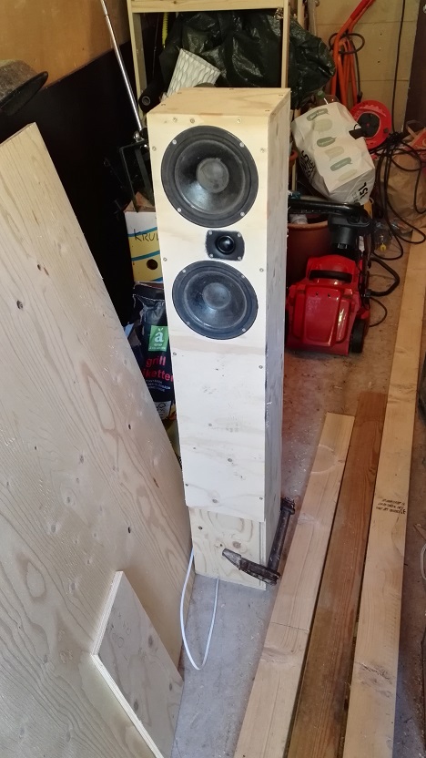
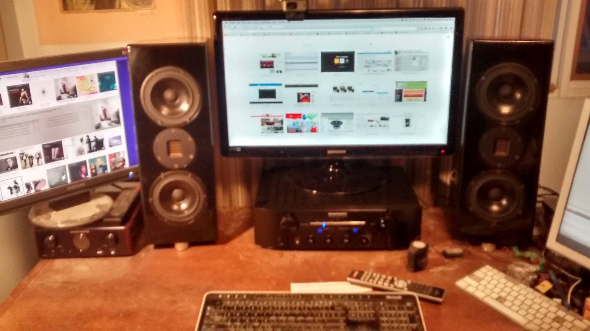
I've put together a simple enclosure (~30 l) that for the moment is heavily stuffed and open in one end (just to make measurements for XO-design). It looks like this:
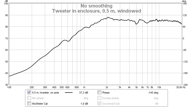
All measurements are gated at 9 ms (before first reflection) and done at 1.8 m above ground and at 0.5 m distance. Here is how the tweeter measures in the enclosure:
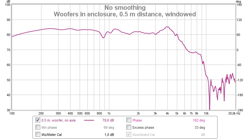
And the woofers (paralleled):
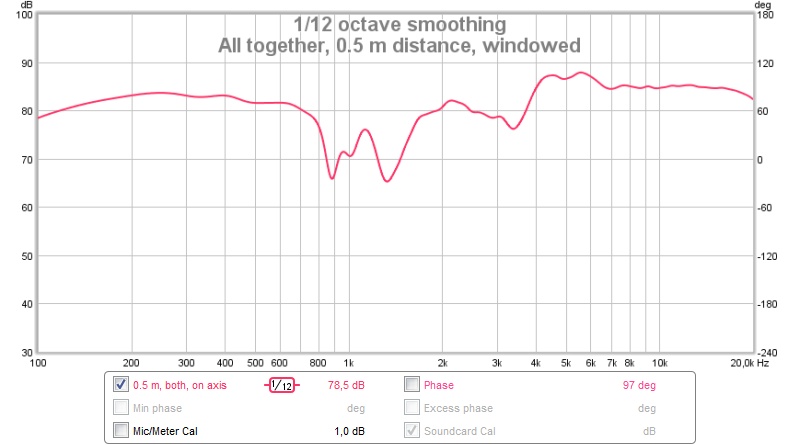
If I run them together without XO I get this (smoothed like in XSim):
I read the whitepaper and like the method, but as I'm able to get a clean 9 ms window I don't really need to splice the curves for an XO above 1.5 kHz. I also tried using PCD, but excel is so painstakingly slow on my computer that I went nuts trying to use it.
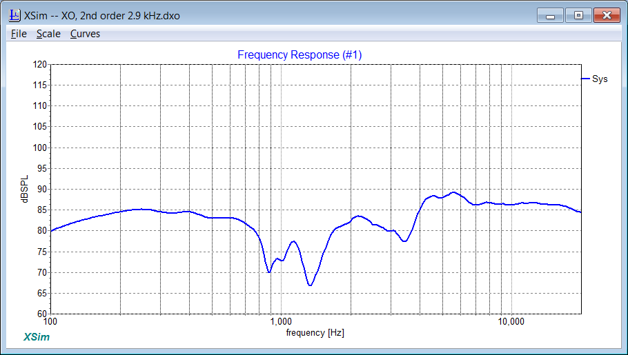
Here is how XSim simulates no XO (at 0.5 m):
Good agreement.
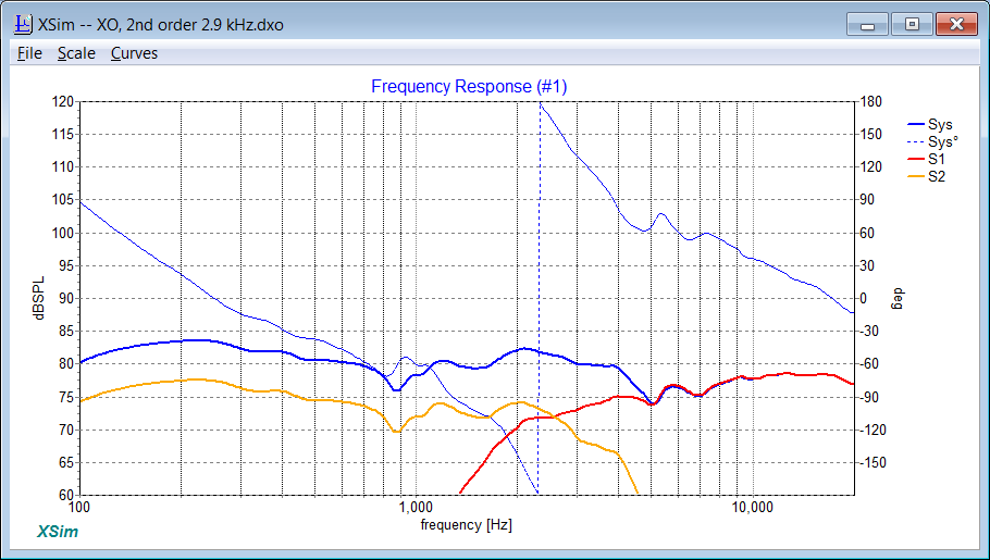
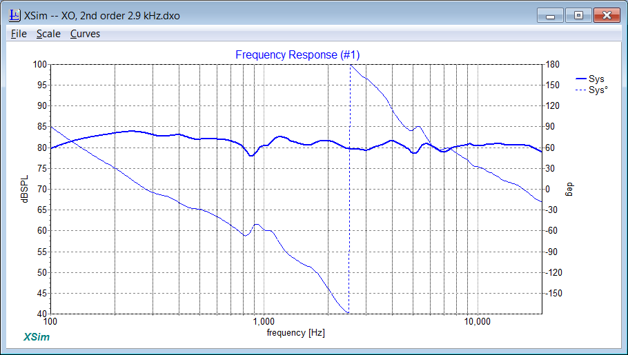
Here is with the XO in system7's post:
And here I've tweaked it to get a flat response:
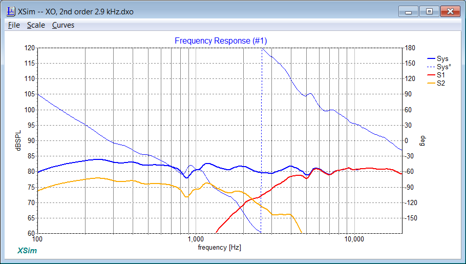
Looks like this:
This is the impedance:
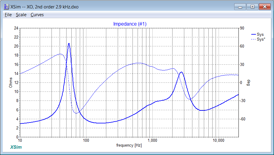
Looks good? I think I have the necessary components in my workshop to make this.
I've attached the new FRD-files if anyone wants to try to make something better. Maybe an asymmetric filter with a third order slope for the tweeter to get better time alignment? The step response for the above filter is not very good.
/Anton
I've put together a simple enclosure (~30 l) that for the moment is heavily stuffed and open in one end (just to make measurements for XO-design). It looks like this:
All measurements are gated at 9 ms (before first reflection) and done at 1.8 m above ground and at 0.5 m distance. Here is how the tweeter measures in the enclosure:
And the woofers (paralleled):
If I run them together without XO I get this (smoothed like in XSim):
I read the whitepaper and like the method, but as I'm able to get a clean 9 ms window I don't really need to splice the curves for an XO above 1.5 kHz. I also tried using PCD, but excel is so painstakingly slow on my computer that I went nuts trying to use it.
Here is how XSim simulates no XO (at 0.5 m):
Good agreement.
Here is with the XO in system7's post:
And here I've tweaked it to get a flat response:
Looks like this:
This is the impedance:
Looks good? I think I have the necessary components in my workshop to make this.
I've attached the new FRD-files if anyone wants to try to make something better. Maybe an asymmetric filter with a third order slope for the tweeter to get better time alignment? The step response for the above filter is not very good.
/Anton
Attachments
-
 IMG_20160830_112255.jpg133.2 KB · Views: 132
 -
 all 0.5 m RAW.jpg67.3 KB · Views: 135
 -
 woofers 0.5 m RAW.jpg70.7 KB · Views: 134
 -
 tweeter 0.5 m RAW.jpg66.8 KB · Views: 131
 -
 response, 2nd order, system7.png39.2 KB · Views: 140
 -
 response, 2nd order 2.9 kHz.png28.5 KB · Views: 130
 -
 filter, 2nd order 2.9 kHz.png14 KB · Views: 142
 -
 impedance, 2nd order 2.9 kHz.png36.5 KB · Views: 130
 -
 response, no XO.png24.6 KB · Views: 137
Last edited:
I realized it's difficult to see the slopes in my proposed XO, so here's the pic with vertical centre moved:

This is the step response:

/Anton
This is the step response:
/Anton
Measurements with filter
I put together a filter according to post #23, except I didn't have any 4.7 Ohm resistors so I used a 3.9 and a 1 Ohm in series (for a total of 4.9 Ohms).
Measured at 1 m:
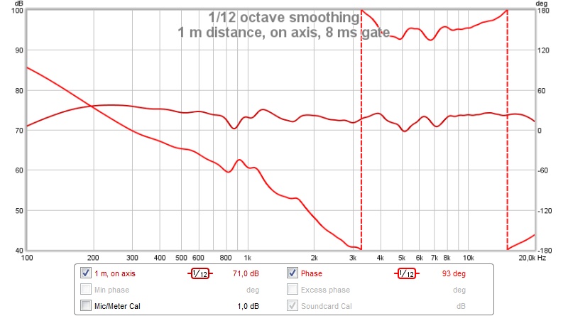
Simulated response:
SPL response is spot on, but the phase for the tweeter is odd. Any guess why?
Comparison of 1 and 0.5 m distance:

Baffle step is more pronounced in 1 m measurement.
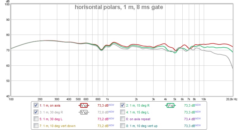
Here are horisontal polars 0, 15 and 30 deg off axis (vertically on axis):
And vertical polars 0, +10 and -10 deg off axis (horisontally on axis):

In total a quite nice result with components that I had laying around. Only thing I needed to do was unwind a few turns on a coil and parallel 10 uF capacitors to make a 20 uF capacitor. Will a TPA3116 have any problem with the impedance dips to around 3 Ohm? Should I buy one that is PBTL (2 x 100 W)? I'm guessing they can produce 100 W at 2 Ohm instead of 50 W at 4 Ohm (standard TPA3116).
I may have forgotten to say that the delay on the woofers is 1.4" (when far away, more if close, i.e. 0.5 m).
Now I'll tune the enclosure and experiment with bass output. Hopefully I can make it reach below 40 Hz.
/Anton
I put together a filter according to post #23, except I didn't have any 4.7 Ohm resistors so I used a 3.9 and a 1 Ohm in series (for a total of 4.9 Ohms).
Measured at 1 m:
Simulated response:
SPL response is spot on, but the phase for the tweeter is odd. Any guess why?
Comparison of 1 and 0.5 m distance:
Baffle step is more pronounced in 1 m measurement.
Here are horisontal polars 0, 15 and 30 deg off axis (vertically on axis):
And vertical polars 0, +10 and -10 deg off axis (horisontally on axis):
In total a quite nice result with components that I had laying around. Only thing I needed to do was unwind a few turns on a coil and parallel 10 uF capacitors to make a 20 uF capacitor. Will a TPA3116 have any problem with the impedance dips to around 3 Ohm? Should I buy one that is PBTL (2 x 100 W)? I'm guessing they can produce 100 W at 2 Ohm instead of 50 W at 4 Ohm (standard TPA3116).
I may have forgotten to say that the delay on the woofers is 1.4" (when far away, more if close, i.e. 0.5 m).
Now I'll tune the enclosure and experiment with bass output. Hopefully I can make it reach below 40 Hz.
/Anton
Attachments


Last edited:
Onni, I think you are doing very well here! 3kHz crossover (actually the -6dB tweeter point with doubled bass drivers, the graph is deceptive...) must be about right. 🙂
We did a 5" MTM recently: http://www.diyaudio.com/forums/multi-way/289344-seas-ca15rly-x2-cabinet-volume-suggestions-6.html
Impedance looks typical for an MTM around 3 ohms at 200Hz: Vifa PL14WJ-
Of course, you have to adapt to the particular drivers. Your tweeters seem to start off high level at low frequency then taper off. Sort of thing that needs an overdamped filter or a third order.
There's many ways to skin a cat. I always look for a decent flattish impedance that doesn't dip too low. Classically tapered 1:3 capacitors here at 8 ohm usually just give the single omega peak that amps don't mind. You can notch that out if fussy with an LCR here marked red.
The symmetric 4 ohm crossover with higher source impedance is not bad either, with a ripple in impedance. Both have the same electrical response, so who knows which is better? But try your second order first. Phase is the other variable, and actually D'Appolito should be done as a 90 degree 18dB/octave BW3 to hit the exact theory, but a hugely complex undertaking, possibly needing time-alignment, in practise. Most people do asymmetric 12dB/octave LR2 or 24dB/octave LR4 and are happy. 😀
Attachments


Last edited:
- Status
- Not open for further replies.