I have an oppo bdp-95, audible illusions m3a, magnum dynalab tuner, Dual 1249 TT and McCormack DNA 0.5, in a closet, in a second floor room where my HT is set up. I have a pair of b&w n803 speakers in a large first floor room. I’m thinking of running a pair of 20 foot long speaker cables, from a speaker selection box, connected to the DNA 0.5.
I was going to make the speaker selection box with one set of inputs. The input cables would be hard wired, to the switch, inside the box and the other cable ends connected to the amp with spades. The switching box would have two pair of selectable output binding posts so I could listen to just, the HT speakers or, the downstairs speakers or both.
The selector box would have a hi-end switch and be point to point wired with 12awg quality wire. The cables, to each pair of speakers, would also be 12awg quality wire. Is there any downside to this set up? The 20 foot runs to the downstairs speakers are my biggest concern. They will be running inside an interior wall with no other wiring in it. All help will be greatly appreciated
Another option i have is to put another amp in the first floor room and run 20 foot long interconnects from the pre-amp in the second floor closet to the first floor amp. I'd prefer using the switching box and 20 foot long speaker cables because I really like the sound of the Mccormack.
My primary question is, what is better. 20 foot long speaker cables or 20 foot long ICs. The ICs would be beldin star quad 1192A which is supposed to have excellent shielding characteristics. I would appreciate any help with this decision.
Thanks,
henrylrjr
My primary question is, what is better. 20 foot long speaker cables or 20 foot long ICs. The ICs would be beldin star quad 1192A which is supposed to have excellent shielding characteristics. I would appreciate any help with this decision.
Thanks,
henrylrjr
Last edited:
20 feet long speaker cables should be no problem, but 20 feet long interconnects could be, if they are unbalanced. You say that you are using star quad cable which is normally associated with balanced working.
In a balanced system the noise immunity comes from the balanced drivers and receivers rather than the cables. A truly balanced system would work quite happily with unshielded twisted pair over 20 feet.
What I am saying is that if you do not have balanced inputs and outputs (XLR connector equipped?) using star quad cable may not be any different to plain shielded wire. The implication being that you may loose some high frequencies due to cable capacitance, depending on the source impedance of your signal sources.
Keith
Thanks for the info. The Audible Illusions M3A, in the 2nd floor closet, only has RCA inputs and out puts.
The amp I have that would go in the 1st floor room has truly balanced inputs. I was thinking, if I went with 20 foot ICS, the star quad wire would be connected to 3 pin male XLRs at the amp end. The RCAs, at the preamp end, would have the star quad negative wires and shield soldered to the negative leg of the RCA. I've seen that type of cable described, on the Modulus86 build site, for connecting and RCA on a preamp to an XLR on the modulus86 amp. Any thoughts on that would be appreciated.
However if 20 foot speaker cables won't be a problem that approach would eliminate the need for a 1st floor amp. I'll be sure to use the best switch, wire and RCAs for the switch box.
Last edited:
Henry, would it be possible to post circuit diagrams of your preamp and power amps?
Can I offer a mini tutorial on balanced connections?
Firstly, the word balanced refers to a two wire connection where the signals appear differentially between the wires, and neither wire is connected to ground. Transformers at each end of the system are regarded as the "gold standard" and the better transformerless designs seek to emulate transformer action. The main attribute of a balanced system is the ability to discriminate between wanted and unwanted signals. The wanted signals are differential (between the wires of the pair) and the unwanted signals are picked up longitudinally (common mode) along the length of the cable. At the receiving end the unwanted hum etc signals are of like sign (in phase) so they are ignored by the transformer primary or rejected by a difference amplifier.
In the early days of transformerless balanced there was much missunderstanding of some basic principles. It was believed that the wanted signals had to be applied in equal amplitude and opposite phase to the wires of the pair re ground. An AES committee on interconnect standards led by Jim Brown and Bill Whitlock showed that this is incorrect. The noise immunity comes from the Wheatstone bridge nature of the circuit impedances and signal symetry has nothing to do with it.
I mention this as it may provide a window of opportunity, in your case, to implement an "impedance balanced" system. Let's say the output source impedance of your preamp is 100 Ohms. We connect the RCA inner to XLR pin 2 and we connect another 100 Ohm resistor between RCA outer shell and XLR pin 3. Pin 1 is shield and is connected to the metal work at both ends.
The other subject is high frequency loss due to cable capacitance, something that is made worse by star quad cable, unfortunately. Whether balanced or unbalanced, we have the potential to make a first order low pass filter with the series R of the source resistance and the shunt C of the cable capacitance.
The Rane Corp Web site has/had? some material on this.
There is information/tutorials by Bill Whitlock on the Jensen transformer site.
Chips made by THAT Corp represent the current state of the art in transformerless balanced should you be interested in grafting some modifications on to your preamp.
Keith
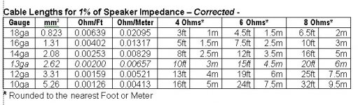
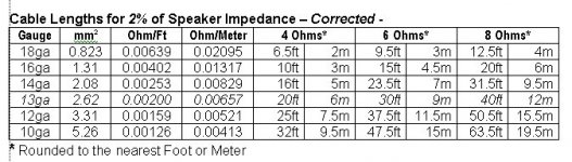
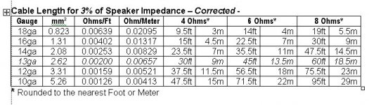
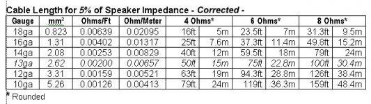
Here are charts for Wire Length based on Gauge and Speaker Impedance for various Percentage of Signal Loss. Keeping in mind that up to 5% Signal Loss is considered acceptable.
You can look up the proper lengths for RCA cable. If you are using decent cable, I don't see roughly 20ft as a problem.
As to speaker wire, I don't see 20ft as a problem. When you get closer to 50ft, the Inductive Impedance starts to trim away at high frequencies though. So on general principle, nothing over 50ft is recommended.
Steve/bluewizard
Attachments
Now that the charts are on line, it makes it easier to post full sized versions -
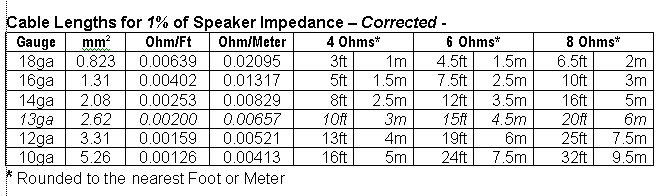

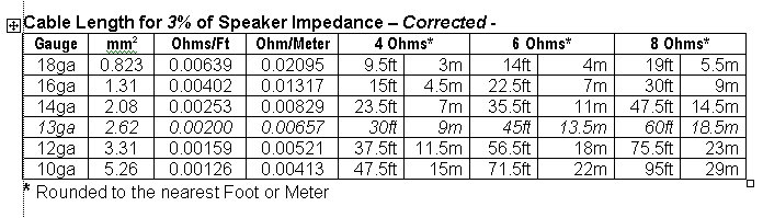

In Europe the common wire is based on Cross Sectional Area and is 2.5mm², which is closest to 13ga (2.62mm²).
Back to the RCA-RCA Cables, you want decent cables with decent shielding. The cheap Dime-Store variety are thin and with very poor very minimal shielding. However, just about any reasonable modestly price RCA Cables will be sufficient.
BELDEN would certainly fall in to the catagory of sufficient cable.
Steve/bluewizard
Based on this Webpage, which is certainly not definitive, you can go a maximum of 30m (100ft) for RCA Audio. Though I think I would not go quite that far.
Going The Distance - A Guide to Maximum Cable Lengths - Cable Chick Blog
The point is, like 20ft to 30ft (10m) of good quality cable would not be a problem, or would be a minimal problem.
Steve/bluewizard
Going The Distance - A Guide to Maximum Cable Lengths - Cable Chick Blog
The point is, like 20ft to 30ft (10m) of good quality cable would not be a problem, or would be a minimal problem.
Steve/bluewizard
Hi,
IMO no preamp output will drive the capacitance of 20ft long
cables well, and if its a parallel feed to your power amplifier, the
said arrangement will severely degrade the main systems treble.
(I found that with a 3m lead to a sub from my pre-outs.)
So go for 20ft long speaker cables IMO.
rgds, sreten.
Thanks for all the replies and suggestions. I'm going with 20ft 14awg speaker cables, from the amp in the 2nd floor closet, to speakers in a 1st floor room.
All components, for the 2nd floor HT and 1st floor stereo speakers, will be in the 2nd floor closet and all ICs will be 1m long or less.
There will be a, A, B or A+B, speaker selection switch in the closet. Volume control in the 2nd floor will be via the Audible Illusions preamp.
Volume of the 1st floor speakers will be via OPPO's remote volume control.
I like this setup because I don't like components visible in a room. Only a stereo pair of speakers and sub will be in the 2nd floor HT room and only a stereo pair of speakers will be in the large 1st floor room.
Thanks,
henrylrjr
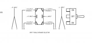
The switch and wires will be in a small chassis and I'll probably use Speakons for connections. Does the attached sketch make sense?
Thanks,
Henry

Looks generally good. Signal come in the center posts and goes out on either end depending on which speakers are active.
A few cautions, though minor and probably not actually a problem.
Break Before Make - there are two type of switches -
- Break Before Make, which is what you want. In this case, the old connection is broken before the new connection is made. This is the most common type.
- Make Before Break, which is much less common. In this case, the new contact is made before the old contact is broken. There are applications that require this, and this would not be one of those cases.
Your switch drawing says ON-OFF-ON, so it is a three position switch with a position in the middle with no contact? If so, then you can be sure it is a Break Before Make.
Next - Slide vs Points
- Slide contacts are what you want. In this case, when the switch is toggled, the contacts slide across the switch and make contact on the other side.
- Point contact have a tendency to bounce. These are like the points in a car's distributor, if you are old enough to remember that. Inside the switch is a rocker with Point-type contacts. The Rocker pivots from the middle like a see-saw or teeter-totter and when the switch is toggled, the points are pressed down on one side or the other. These will work, many household electrical switches are like this. But they do tend to bounce and they can arc if the voltage or current is high enough. We don't care about the fidelity of household electricity, but the arced switch points could degrade the sound quality.
Also, Point Contacts are the opposite ot the toggle, that is, when the switch is toggled to the right, the contact is made on the left.
The Slide switches tend to not bounce, and each time the switch it toggles the contacts tend to wipe themselves clean. And because there is no bounce, there is really little to no tendency for the contacts to arc.
Make sure the switch is overrated for Current. A 100w/ch amp can have about 50v available on the outputs, if we push the full 50v into an 8 ohm speaker, then the potential Current is -
Current = SqRt(P/R) = SqRt(100/8) = SqRt(12.5) = 3.54 AMPS
So, you probably want a switch rated at about 6 amps to 8 amps to give you some reserve.
Also make sure the voltage rating is sufficient. If there is a potential for near 50v, then you probably want at least a 100v rated switch.
Just a few thoughts but overall the switch should work.
I notice you are only switching the hot or red leads of the speakers. That's OK 95% of the time, because inside an amp, all the Grounds, input and output, are common to each other. They are all physically and electrically connected.
However, some amps aren't Stereo, they are Dual Mono, in which case, the grounds of each channel are not connected, or potentially are not connected.
Use an Ohm Meter and test for continuity between the two amp output Grounds, it there is virtually ZERO resistance, you are good. It you do measure resistance or an open, then you might want to consider also switching the ground wires.
On this last issue, I'll leave it up to others to confirm or deny, but that is my take on it.
Generally, though I think you are good.
Steve/bluewizard
Last edited:
- Status
- This old topic is closed. If you want to reopen this topic, contact a moderator using the "Report Post" button.
- Home
- Loudspeakers
- Multi-Way
- long speakers cables and selection box