So, I've just recently returned to DIY Speaker building and have a full "kit" for some small monitors already sorted (look at Wayne Jaeschke's DBP HERE). Purchased probably in 2005, if I recall correctly. Yeah, it's been a long time...
But, that's not what my question is about. I have some surpless North Creek Music Systems D25 1" matched tweeters that I'd like to use, very much like Wayne's "PeeCreek" project. Only, since the 850122 wid-woofer is long gone, I've looked into some alternatives.
My best, closest match was the Peerless 830874. I could have gone with the 830883 but hated the silver frame and questionable performance benefit for the price, or even the Nomex version 830875. In the end, the price/performance ratio of the 874 won out. I ordered a pair locally and they've arrived today.
On to my question - I'm not hoping for a drop-in replacement for the old crossovers for the PeeCreek and there are a number of differences between the old driver and the new. I'm getting familiar with PCD again and seem to have worked out a few annoyances (it was built for Excel 2007 after all). However, after tweaking a design and thinking I was the smartest guy ever, I realised I hadn't input any phase data for the drivers.
I went back to Response Modeller and after several attempts, managed to get what I think was an accurate phase curve to import back into PCD.
And then my beautiful response curve fell completely apart...
So here's the question: Is there an accurate source for phase data for a given driver? Furthermore, is there any magic to phase data or can it be determined purely on the FR of a given .frd file? Or .zma for that matter? I'm definitely stumped.
Oh, and if this is the wrong place, please let me know so I can flag it with a mod.
Cheers,
Michael
Hi Michael,
I usually measure the phase and amplitude at the same time. OmniMic has an option to phase restore an FRD file. This is useful when the data is coming from a picture that has been traced.
The acoustical phase is related to the slope of the FRD data, if I recall, so it can be restored mathematically fairly easily.
The electrical phase however is something else, and I"m not sure if it's possible to phase restore it, nor am I sure it matters. That's something I haven't thought about.
It's very important to have the acoustical phase, but you need to know not only the phase vs. frequency, but also the inter-speaker distance. Please read about measuring that on my blog page here. The speaker's natural response + distance is necessary to compute a crossover's final response accurately.
Also, please check out the LM-1 project I just published. About $470 if you buy the cabinets, about $300 if you build them yourself.
Best,
Erik
Thanks very much for the info Erik!
I should have mentioned I've got a very good grasp on driver distance, driver placement on the baffle, size of baffle, and driver depth. Well, a good grasp on how they all can affect response.
What I specifically wanted to know was how the FRD data can possible predict phase, the way the extraction tools seem to suggest.
I've got one of those little iMMC mics from Dayton audio to play with when I get moving on this little project.
My plan at the moment is to define enclosure completely, cut all the wood for the enclosures and then get to work on the crossover, perhaps even using the measurement analysis tools and mic to do it all in sync.
I'll have a look at your blog and see what else I can soak up. Thanks again!
Fascinating. I understand the whole damping, vs radiator size, vs frequency relation but wasn't sure phase could be "read" from a simple FR curve. I'll have to play around a bit more with the modelling software to see if I can make it all match up with my (limited) knowledge at this point.
Measuring can be a good idea, as not all of the sound will be coming straight from the driver. A reconstruction may not be all you expect it to be. Additionally, you won't need to worry about driver distances.I've got one of those little iMMC mics from Dayton audio to play with when I get moving on this little project.
Technically phase its not related to amplitude but to the rate of change of amplitude, if i remember correctly.
Yes. In minimum-phase systems, say all systems which have only one signal path (what excludes interference, as interference is due to several signal paths interacting), phase is derivation, steepness, rising/falling angle of the plot of amplitude versus frequency, if both amplitude and frequency are shown on logarithmic scale.
Electroacoustic drivers are minimum-phase at low frequencies. If their size approaches wavelength, it becomes different especially off-axis. It must, for else multi-way loudspeakers would hardly work off-axis at all.
I managed to find some of the PartsExpress catalogue extractions from Clio that someone archived ages ago (HERE).
Why do I need old, archived responses? Because I want to "sanity check" my understanding of PCD first, by using the original drivers in the PeeCreek, along with the details of the original kit, as measured by the designer. Then I can look at the driver phase and see if what I get from extracting the phase, matches up with what the modeled response and measured response showed on the site. Granted it's not exact but if it's ballpark, I will know that my own, new project at least is being put into the simulation correctly.
Why do I need old, archived responses? Because I want to "sanity check" my understanding of PCD first, by using the original drivers in the PeeCreek, along with the details of the original kit, as measured by the designer. Then I can look at the driver phase and see if what I get from extracting the phase, matches up with what the modeled response and measured response showed on the site. Granted it's not exact but if it's ballpark, I will know that my own, new project at least is being put into the simulation correctly.
...Just hit some random key combination and lost a fairly lengthy update to this thread. Oops..
So I'm in the final stages of building and have decided to buy the drivers first, settle on an enclosure (I'll likely be going sealed for better integration with my sub, as well as ease of designing the cabinets). My final task will be to test the drivers mounted in the boxes and then (and only then) will I start working on the crossover design.
This will be the first time I've ever done it this way but I think it's the best way to make sure I get exactly what I want to make this all work best.
I've played around enough with the various Excel tools to get to where I think I'm proficient enough to make this all work out well. Thanks for the pointers and the help so far, all! I'll post a new thread when I start construction.
While this isn't an update to the original design of the Peerless/Northcreek system I'd specifically mentioned in the opening post, it is somewhat related.
I built 4 cabinets with the intention of doing 2 as described above, and the other two as rear surround duty, with two very cheap drivers: the Dayton shielded paper cone 5.25" woofers and the old shielded "Silky" tweeter. Both were purchased when shielding was a good idea. So they're VERY old but hadn't been touched so are "new" to me.
A few months in and the Dayton Budget drivers are now happily in my system as rear channels, just like I'd planned.
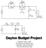
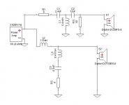
Funny thing about how I progressed with my questions about modelling vs real measurements and phase relationships. Here's what I settled on for the crossovers for the DBP.
First, the as designed one from Wayne Jaeschke (with some nice attention to the peaking on the driver):
My modified version:
Simulated response using PCD 7.
Normal:
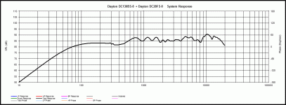
Reversed Tweeter:
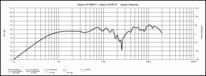
Measured response using REW.
Normal:
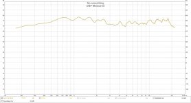
Reversed Tweeter:
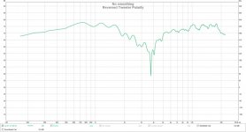
Bear in mind, the imported response curve was using the measured response with a (probably very poorly done) simulated low end response below about 400hz.
The crossover:
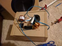
And the two speakers, completed(ish):
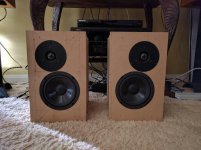
Point? The reverse null is pretty extreme and the overall response, while a bit lumpy and certainly not the best shape, is actually not too bad.
I built 4 cabinets with the intention of doing 2 as described above, and the other two as rear surround duty, with two very cheap drivers: the Dayton shielded paper cone 5.25" woofers and the old shielded "Silky" tweeter. Both were purchased when shielding was a good idea. So they're VERY old but hadn't been touched so are "new" to me.
A few months in and the Dayton Budget drivers are now happily in my system as rear channels, just like I'd planned.
Funny thing about how I progressed with my questions about modelling vs real measurements and phase relationships. Here's what I settled on for the crossovers for the DBP.
First, the as designed one from Wayne Jaeschke (with some nice attention to the peaking on the driver):

My modified version:

Simulated response using PCD 7.
Normal:

Reversed Tweeter:

Measured response using REW.
Normal:

Reversed Tweeter:

Bear in mind, the imported response curve was using the measured response with a (probably very poorly done) simulated low end response below about 400hz.
The crossover:

And the two speakers, completed(ish):

Point? The reverse null is pretty extreme and the overall response, while a bit lumpy and certainly not the best shape, is actually not too bad.
An externally hosted image should be here but it was not working when we last tested it.
I never did update this little project of mine. Might even want to change the title (if that's possible).
I officially finished up the rear surrounds last night with the completion of the last bit: grills. I'd been using them without any protection for over a year now but having children around and the proximity of the speakers to the corners of my couch, meant I needed to address this last little detail.
Some of the missing pictures from the last post till now, starting with the "completed" mini speakers in the state they'e been in for about a year:
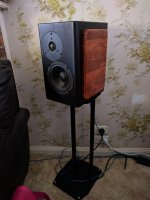
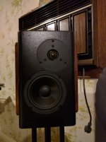
I worked quite a lot on the finish, starting with an overall sanding sealer coating, followed by water based white primer, then some outdoor black fence paint in a nice satin sheen. A word of advice on the sanding sealer, it's really only a good idea on the cut surfaces of the MDF. Anywhere else and it was just too waxy, greasy, and meant the paint was peeling off constantly. The white was also something I think I'll skip next time. I just don't know how necessary it was.
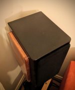
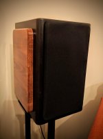
The side "cheeks" are Ikea Birch chopping boards that I attempted to cut down to a workable size. I was limited to what I could use, based on the direction I wanted the grain to run (front to back) and the width of the boards. It's certainly different.
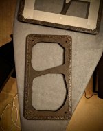
And here's a few in progress shots of the grills:
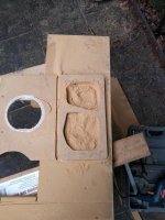
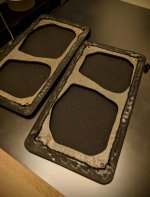
That ridiculous shape is to allow for the offset of the woofer and tweeter and the middle bit to provide some strength. The frame is 6mm MDF and there's a 45 degree chamfer around the edges of every surface, about half way down the edge. Still, I'm guessing there's a fair bit of reflection that will be happening with these openings. Might experiment with some felt later on. The pic shows two grills, as I cut one and then used a heavy top bearing straight cutter in the router to make a duplicate.
Test fitting:
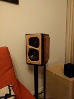
Painted, and ready for fabric. I marked out an edge with masking tape, applied some hot melt glue in a somewhat even pattern, removed the tape and then went on to applying the fabric with the help of an iron.
All finished:
I officially finished up the rear surrounds last night with the completion of the last bit: grills. I'd been using them without any protection for over a year now but having children around and the proximity of the speakers to the corners of my couch, meant I needed to address this last little detail.
Some of the missing pictures from the last post till now, starting with the "completed" mini speakers in the state they'e been in for about a year:


I worked quite a lot on the finish, starting with an overall sanding sealer coating, followed by water based white primer, then some outdoor black fence paint in a nice satin sheen. A word of advice on the sanding sealer, it's really only a good idea on the cut surfaces of the MDF. Anywhere else and it was just too waxy, greasy, and meant the paint was peeling off constantly. The white was also something I think I'll skip next time. I just don't know how necessary it was.
The side "cheeks" are Ikea Birch chopping boards that I attempted to cut down to a workable size. I was limited to what I could use, based on the direction I wanted the grain to run (front to back) and the width of the boards. It's certainly different.
And here's a few in progress shots of the grills:

That ridiculous shape is to allow for the offset of the woofer and tweeter and the middle bit to provide some strength. The frame is 6mm MDF and there's a 45 degree chamfer around the edges of every surface, about half way down the edge. Still, I'm guessing there's a fair bit of reflection that will be happening with these openings. Might experiment with some felt later on. The pic shows two grills, as I cut one and then used a heavy top bearing straight cutter in the router to make a duplicate.
Test fitting:

Painted, and ready for fabric. I marked out an edge with masking tape, applied some hot melt glue in a somewhat even pattern, removed the tape and then went on to applying the fabric with the help of an iron.


All finished:


Last edited:
- Status
- This old topic is closed. If you want to reopen this topic, contact a moderator using the "Report Post" button.
- Home
- Loudspeakers
- Multi-Way
- Designing a Crossover for a Mini Two Way, How Important is Driver Phase Response?